

In this article, I will be sharing with you…
- how to get started with NodeMCU ESP8266 development board
- how you can program it easily using good old Arduino IDE and take your project to next level with WiFi connectivity.
Before we get started, I assume that you have a basic knowledge about Arduino and its development environment. If you need a refresher, check out the Simple Guide to Arduino, first.
So without wasting any more time on the introduction, Lets get started!
Introduction to NodeMCU (ESP8266)
The ESP8266 is a low cost microcontroller with on-board WiFi functionality. Here are the technical specifications.
Specifications:
- Operating Voltage : 3.0 ~ 3.6V
- Average Operating Current : 80mA
- Tensilica Xtensa LX106 32 bit RISC CPU running at 80 MHz
- 16 GPIO Pins
- SPI
- I2C
- I2S
- UART – 2x TX and 1x RX
- 1x 10bit ADC
- Operating Temperature : -40°C ~ 125°C
- Frequency Range : 2400 ~ 2483.5MHz
This can be used in multiple projects like Home automation, WiFi controlled Robots, weather stations, and more.
Materials for this Project
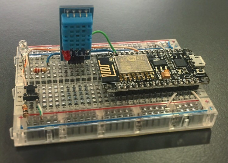
Hardware Components
Software
That’s everything we need, Let’s move on to the next part to set up the IDE.
Set up the IDE for NodeMCU
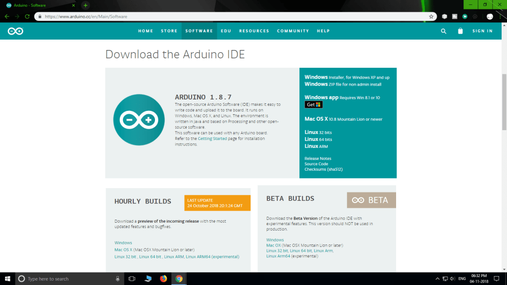
First, download and install the Arduino IDE from the Arduino website. You can also use the Learn Robotics Cloud IDE if you’d like the flexibility from programming in the browser!
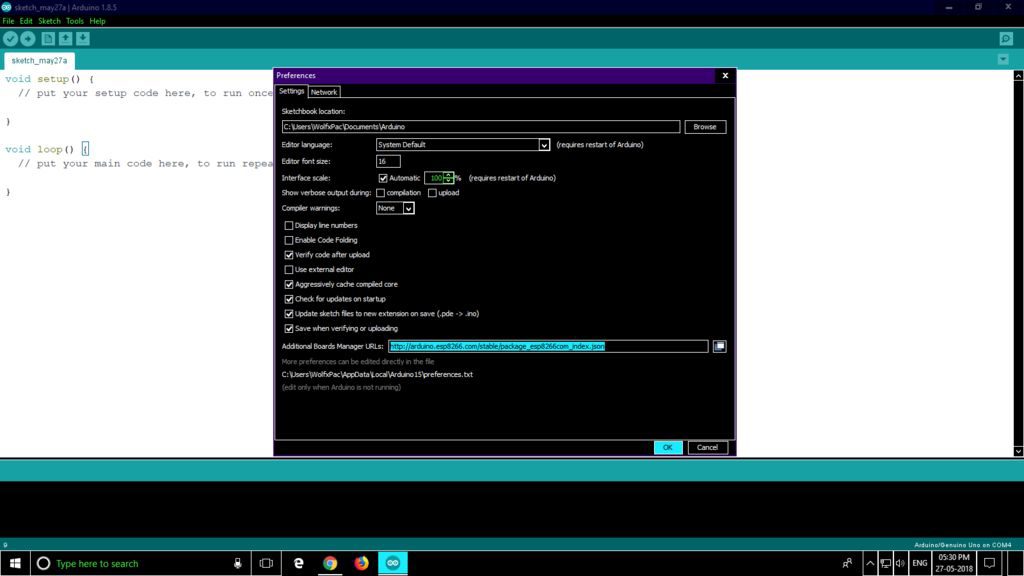
Now to program the ESP development board, the Arduino IDE should have list of boards. For that we have to install all the ESP boards. First Goto >> Files >> Preferences >> and paste the following link in ‘Additional board manager URL’s‘ and click on ‘OK‘.
https://arduino.esp8266.com/stable/package_esp8266com_index.json
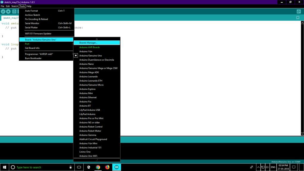
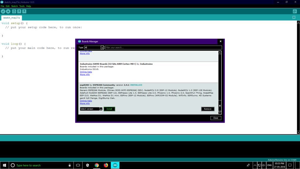
Then, Goto >> Tools >> Board >> Board Manager.
Scroll down to find ‘ ESP8266 ‘ install it.This will add all the ESP based development boards to the IDE.
Now to connect the NodeMCU to your PC, you have to install CP210X driver. Download the latest version compatible to your OS from this website. Select the right board from the downloaded list. In this article I have used NodeMCU 1.0 (ESP-12E Module), so I will select that.
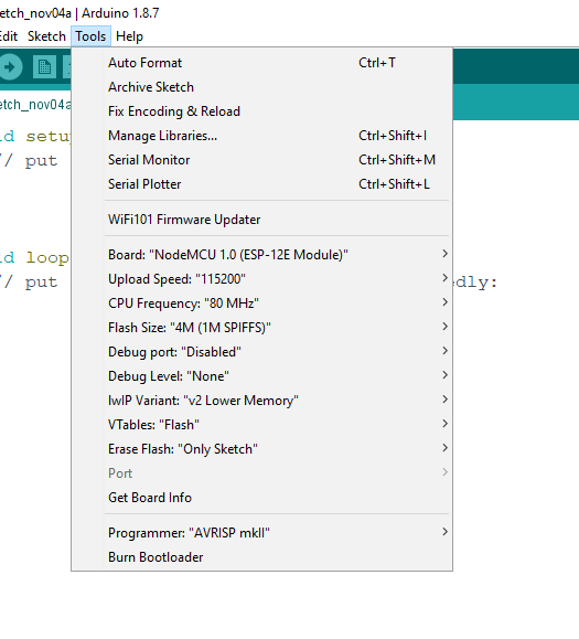
Goto >> Tools >> Board >> Select the ESP board you have.
After selecting the correct board, keep the settings as follows:
- Flash Size : “4M (3M SPIFFS)”
- Debug Port : “Disabled”
- Debug Level: “None”
- IWIP Variant: “V2 Lower Memory”
- CPU Frequency: “80Mhz”
- Upload Speed: “921600”
- Erase Flash: “Sketch On”
- Port : “COM port available” (where the device is connected should show up)
Now the board is ready to be programmed.
Upload the Sketch to NodeMCU
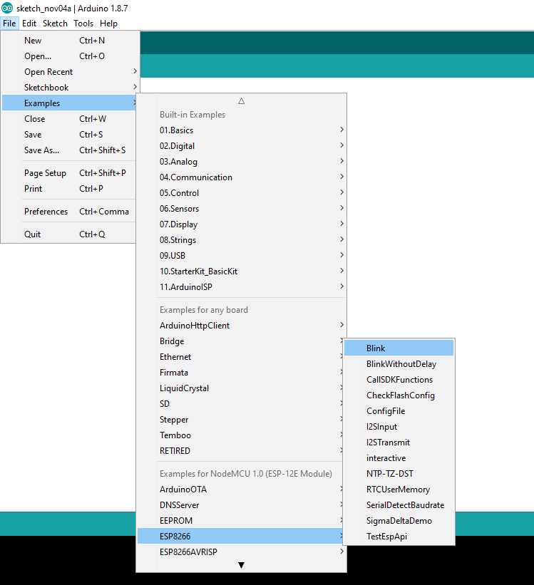
Now that the IDE is setup for NodeMCU you can test it by uploading an Example sketch as follows :-
- Files >> Examples >> ESP8266.
- Select the Blink example and upload it.
The on board LED should start to blink. Now the on board LED is connected to Pin D0 of the MCU. You can connect an external LED to the pin D0.
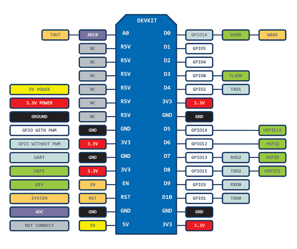
Now to write sketches for NodeMCU you should know the Pins as NodeMCU have different pin mapping. You can either use D0…D10 or use the following :-
- D0 = 16
- D1 = 5
- D2 = 4
- D3 = 0
- D4 = 2
- D5 = 14
- D6 = 12
- D7 = 13
- D8 = 15
- D9 = 3
- D10 = 1
Hope you enjoyed this post and found it informative. If you have any questions, you can ask them in the comments, below. Next time we will see how Projects can be controlled over the Internet through your Web Browser.


7 Responses
I followed your instruction. But with three boards I always get the failure-notice that there is no board connectet. The Port-display is always grey.
It’s possible you need the CH340/CH341 driver installed. Check the datasheet for your board. ~Liz from Learn Robotics
Once connected, do you have a tutorial on how to implement the WIFI conectivity?
Hey Randy, yes we do. Check this out: 3 Steps to Connect an ESP8266 to WiFi