

Previously, I posted a tutorial about home automation where I showed you how you can control relays over the internet using an Android app. In this article, I will show you how to configure your home automation system using Google Assistant and an ESP8266.
In this project, you’ll learn how to build a voice-controlled appliance. We’ll program phrases like “Turn on the lights” or “Switch on the fan.”
[level1]Sounds interesting right?!
You’re probably wondering if this is another tutorial for Android users. But that’s not the case! Google Assistant is now available for iOS on the App store. So, everyone regardless of smartphone type can take part in this home automation project using Google Assistant.
Before we get started, I recommend reading the following articles:
These posts will give you a general idea about the Web Apps we’ll be using.
If you are into IoT and Robotics, be sure to check out my eBook, “Mini WiFi Robot.” This eBook will take you through all the steps through designing, building, and coding your very own mobile robot.
[products ids=”10481, 9719″ columns=”2″]With that said, let’s get started.
Components for Home Automation with Google Assistant
Here is a list of all the hardware and software components we need:
Hardware Components
- ESP8266 dev board
- Relay module
- Breadboard for prototyping
Software Components
- Account at RemoteMe.org
- Account at IFTTT
- Arduino IDE
- Google Assistant for Android or iPhone
Creating Variables and Devices
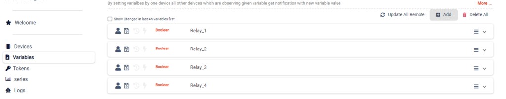
First, we have to create a few variables that will control our relays. To create variables, sign in to your RemoteMe account and go to “Variables” and click on “Add.” Fill the information as presented below:
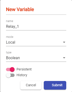
Repeat this process for three more variables for Relay_2, Relay_3, and Relay_4.
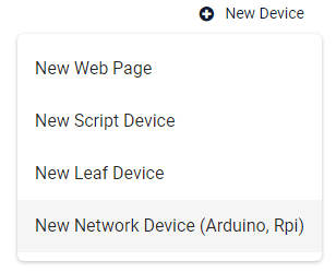
After all the variables are created, we need a network device that will connect to our ESP8266 board. To create a device go to the “Devices” tab and click on “New Device.” From the drop-down menu select the last option “New Network Device.”
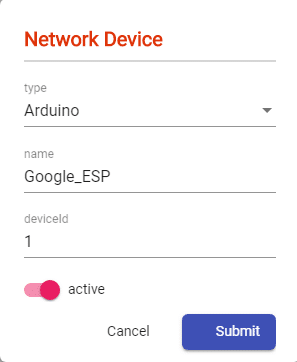
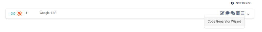
Here we need to name our device. I suggest using the same names as above so that you’re not confused while coding. Let’s name the device “Google_ESP.” The device ID is ‘1’. After these parameters are filled, hit “Submit” to create the device.
Next, we have to generate the code for the device. To generate code click on the burger menu on the device and select “Code Generator Wizard”.
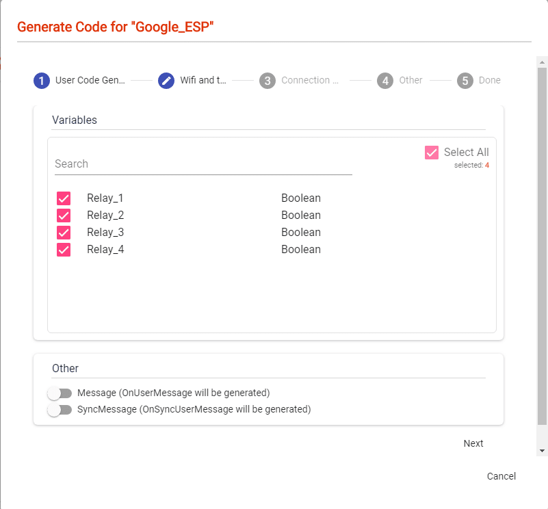
We will see a pop-up window where we have to select the variables we created earlier. Now click on “Next”
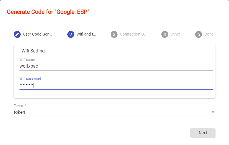
On the next page enter your WiFi credentials so that the ESP can connect to your network.
Next, you can enable a direct connection if you want. This will minimize lag, but it doesn’t matter for this project.
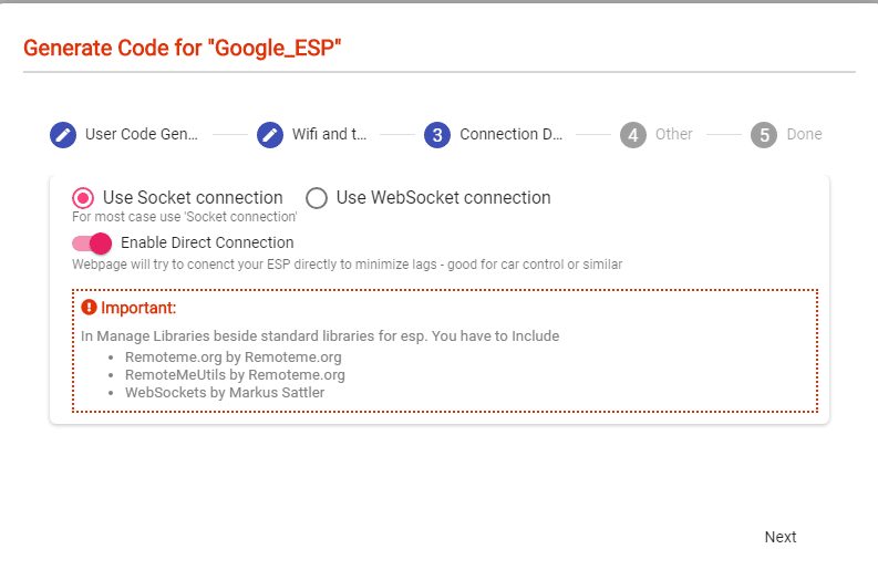
Then, turn on the “Debug” option and click on next.
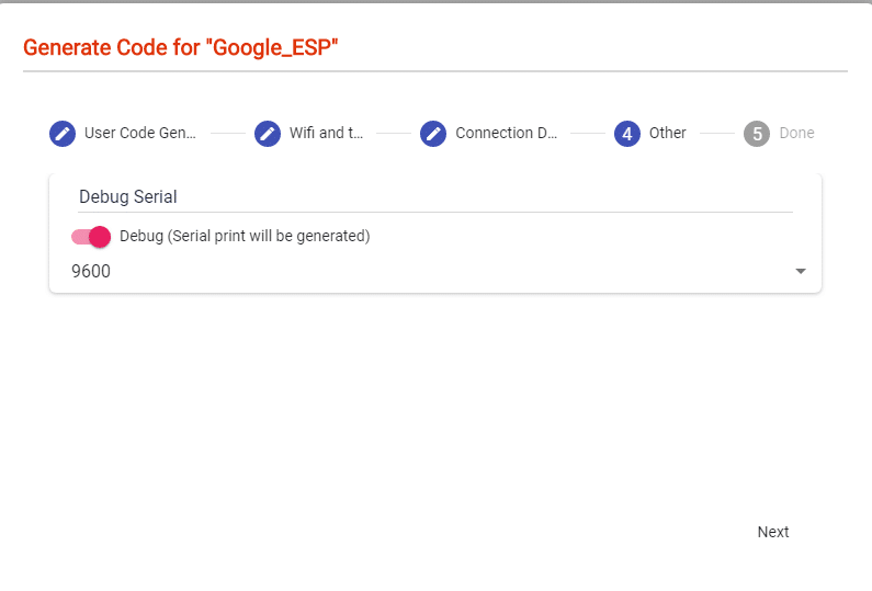
Download the code. We will edit this code in the next step. Lastly, we need one more device. This will be a web device where we can switch on/off our devices.
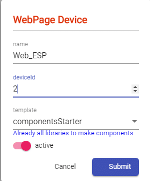
To create the Web page, click on “New Device” and select the very first option “New Web Page”.
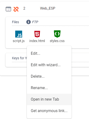
Name the device ” Web_ESP” and give device ID “2” and submit.
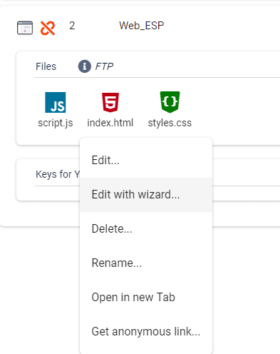
To control the relays we need buttons/switches on the web page. To add this page, first, click on the device “Web_ESP,” and click on “index.html.” From the drop-down list select “Edit with wizard.”
Click on the “Insert Component”, next click on “Components,” and from the list select “Switcher.”
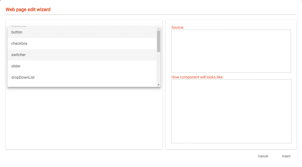
In the name field notice the search icon (magnifying glass). Click on the icon and select “Relay_1.”
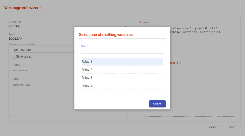
Next, you can label the button anything. I labeled it “Relay 1.”
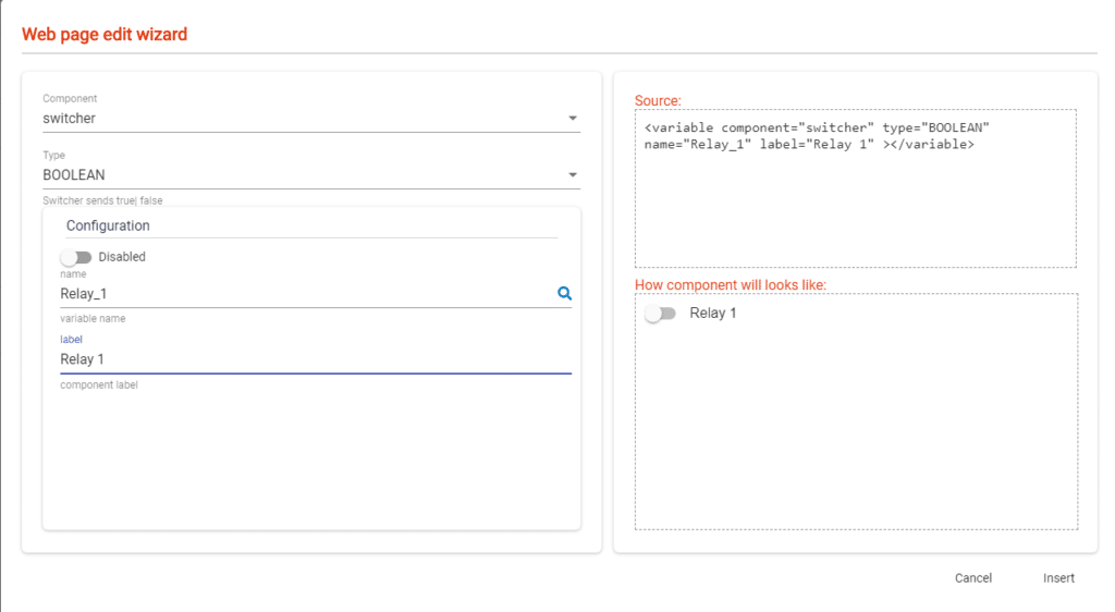
Next click on “Insert” to add the switch.
[level1]Similarly, we have to create 3 more switches for Relay_2, Relay_3, and Relay_4.
Set Up IFTTT for Google Assistant
In the previous step, we created variables and devices. We can use this for home automation, as is, but this is pretty boring.
To make it more interesting, we are going to connect our project to Google Assistant to take voice commands and turn on the relays.
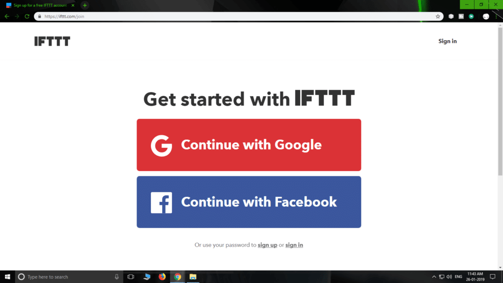
First head over to the IFTTT website, and sign up with your Google account.
Note: Make sure you use the same google account you have on your smartphone or the setup won’t work.
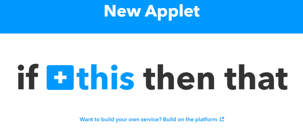
Once you log in, click on “My Applets” and then click on “New Applet”

On the page, you will see a heading, “If this then that.” Click on “+this”
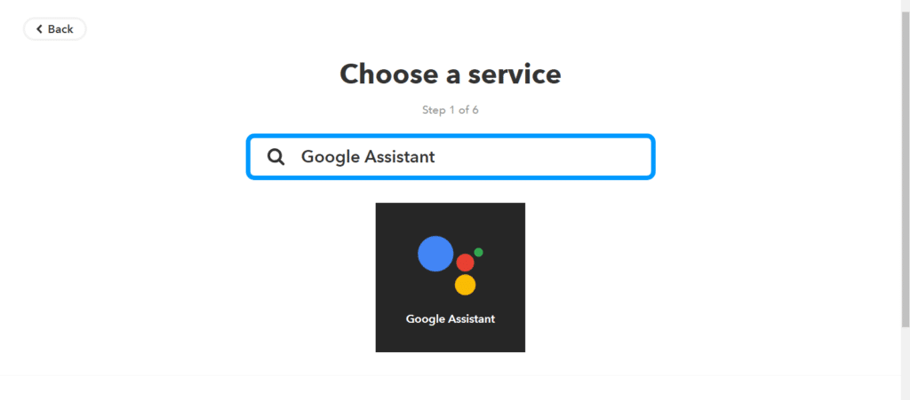
In the search box type “Google” and select the “Google Assistant.”
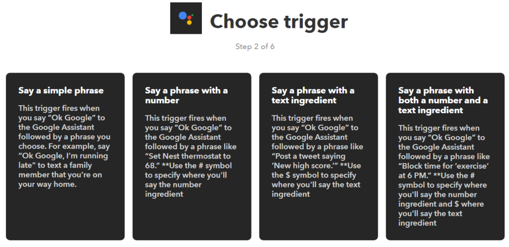
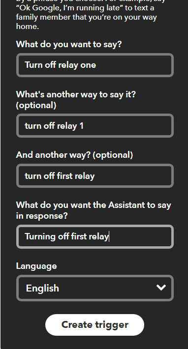
Now select the first trigger “Say a simple phrase.”
Here we will add some phrases we want the assistant to recognize and trigger an action. I used “Turn on relay one” as the trigger, below there are two more options where we can add the phrases in different forms.
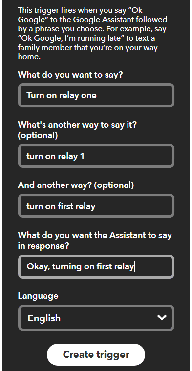
Then, in the last field, we have to add a response phrase that the Google Assistant will use to give a reply. I used “Turning on relay one.” You can customize these phrases as you’d like.
Now click on “Create Trigger” to finalize the trigger.
Lastly, select “that.” Now, we will create what happens when the trigger is set.
 In the search bar type “web” and select “Webhooks.”
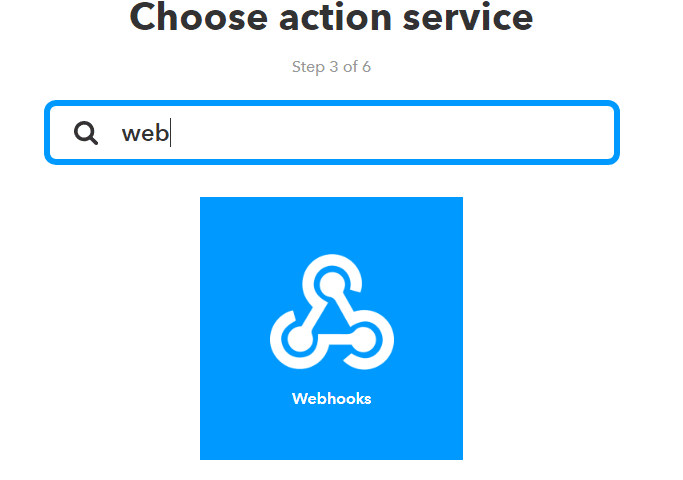
Click on “Make a web request.”

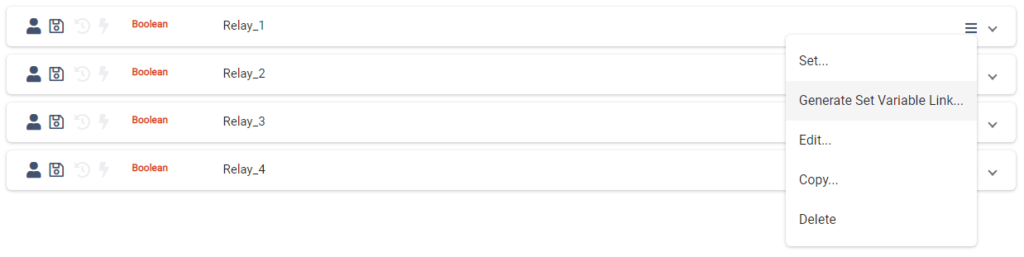
Now go back to RemoteMe and go to the “Variables” tab.
Click on the burger menu on “Relay_1,” and click on “Generate Set Variable Link.”
Toggle on “use post method” and “Boolean”, Click on “GENERATE.”
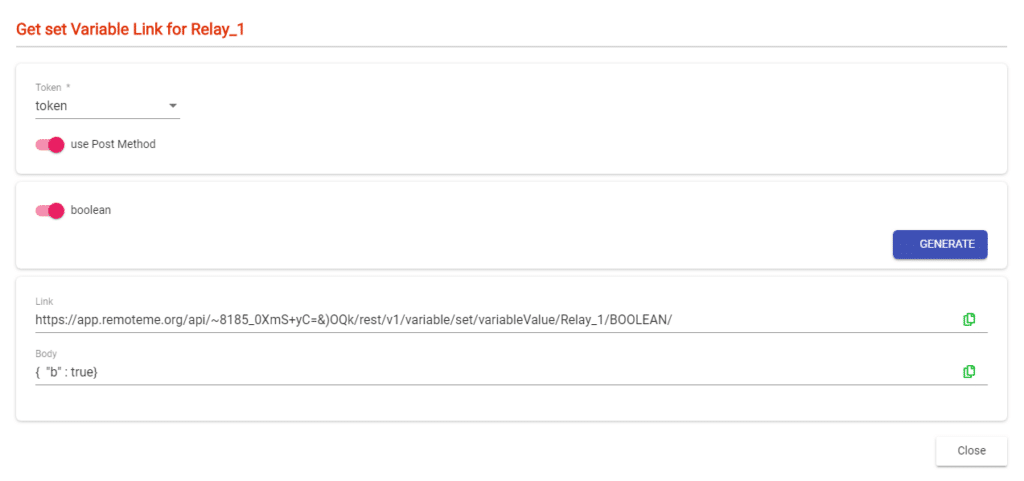
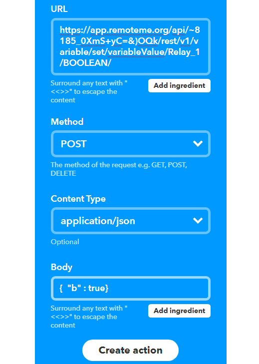
Copy the link from RemoteMe, and head over to IFTTT. In the URL field paste the URL you just copied. Select “POST” under Method, and content-type “application/json.” Now from RemoteMe, copy the body section and paste it in the body field on IFTTT. Click on “Create action,” and “Finish” to make the Applet.
Now go to “My Applets,” and create a new applet the same as the previous step. This applet will be used to turn the relay off. Adjust the phrases so that they make sense. Instead of a response “Turn on relay one,” change it to “Turn off relay one.”
In Webhooks paste the same URL link and select method as “POST” and content type as “application/json.” We’ll use the same body as before but replace “true” with “false” in the body section. Then hit “Create Action,” and “Finish” to create the Applet.
Similarly, make Applets for each relay with proper phrases. You should get 8 Applets in total for 4 relays.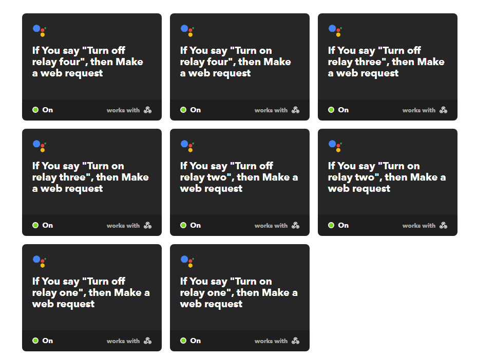
With that complete, we are all set to edit and upload the code downloaded in the previous step.
Editing and Uploading Code
Open the code downloaded from RemoteMe. We have to edit the code a little to fit our requirements.
First, we have to define the pins we will use as output.
#define Relay_1 D1
#define Relay_2 D2
#define Relay_3 D3
#define Relay_4 D4
Now scroll down, and you will find four functions something like “void onRelay_1Change“. Here add the following line:
digitalWrite(Relay_1, b ? HIGH : LOW);
Add this line in all four functions, just replace “Relay_1” with 2, 3, 4, respectively.
void onRelay_1Change(boolean b){
  Serial.printf("onRelay_1Change: b: %d\n",b);
  digitalWrite(Relay_1,b ? HIGH : LOW);
}

void onRelay_2Change(boolean b){
  Serial.printf("onRelay_2Change: b: %d\n",b);
  digitalWrite(Relay_2,b ? HIGH : LOW);
}

void onRelay_3Change(boolean b){
  Serial.printf("onRelay_3Change: b: %d\n",b);
  digitalWrite(Relay_3,b ? HIGH : LOW);
}

void onRelay_4Change(boolean b){
  Serial.printf("onRelay_4Change: b: %d\n",b);
  digitalWrite(Relay_4,b ? HIGH : LOW);
}
Scroll down to find the setup function. Here we have to set the pin mode to output.
pinMode(Relay_1, OUTPUT);
pinMode(Relay_2, OUTPUT);
pinMode(Relay_3, OUTPUT);
pinMode(Relay_4, OUTPUT);
Also, we have to set the pins LOW, so the relays don’t turn on after powering the module.
digitalWrite(Relay_1, LOW);
digitalWrite(Relay_2, LOW);
digitalWrite(Relay_3, LOW);
digitalWrite(Relay_4, LOW);
With those changes complete, the code is ready to be uploaded to the ESP8266.
Download a copy of the sketch by entering your email below. Then you can add your WiFi name, password, and the token from RemoteMe.
Here’s your download!
Download Arduino Sketch (.ino)
Wiring Diagram for Home Automation Project
Connect components using the wiring diagram, below. You can download the Fritzing file and make modifications, as you’d like.
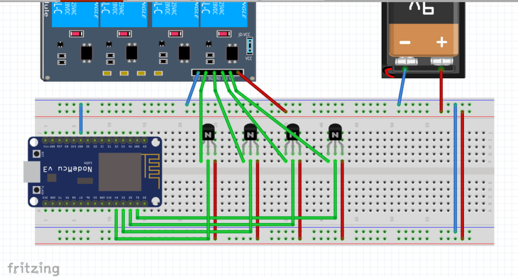
- Connect D1, D2, D3, and D4 of ESP8266 to IN1, IN2, IN3, and IN4 of the relay module.
- In the diagram, I have used transistors as a switch to control relay.
- To power the Relays, connect a 9v battery.
- If you want to power the ESP board, connect a 9v battery to Vin pin. I powered it over USB.
- Make sure the GND pin of ESP is connected to the GND pin of the Relay module.
Connect the Relays (Use caution)
To turn on/off an appliance, we have to connect it to the other end of the relay.
Check out the connections in this article for more details. To make the connections to the relay, follow the steps given below.
First, we have to find the live wire and cut it in the middle to attach it to the relay. To find the live wire you can use a wire tester.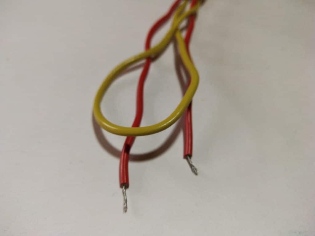
Connect one end of the wire to the middle terminal of the relay and another wire to the normally open terminal.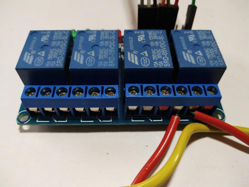
Now you can plug it in, and start controlling it using your browser or google assistant.
[level1]Testing the Google Home Assistant
To test the build, first power up the ESP and the relay module. It will take a few seconds to connect to WiFi. Now almost everyone knows how to use Google Assistant, so I will not explain the process of it.
In short, we can ask Google Assistant to turn on relay one or two. In a couple of seconds, the light should turn on. You can also use the switches we created on RemoteMe.
Follow these steps:
- Head over to remoteme.org and login with your account.
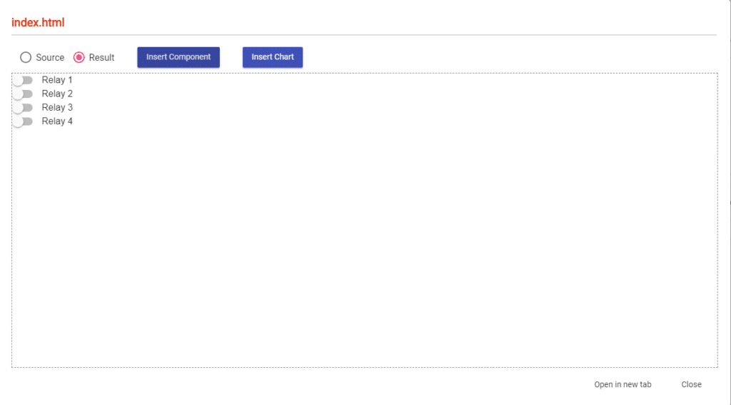
- Go to the “Devices” tab and click on “Web_ESP”
- Now click on “index.html” and select “Open in new tab”
 From the new webpage, it is possible to toggle on/off the relays.

To share the page with a smartphone, select the “Get anonymous link” option from the same list. It will give you a link or click on the QR icon right next to it. It will display a QR code.
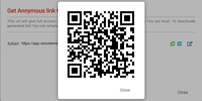
Scan this code using any mobile device and you will be redirected to the “Web_ESP.”
Video Tutorial
What’s next?
You can control more than four devices using an 8ch relay or even a 16ch relay board. The ESP8266 doesn’t have enough pins to control 16ch so you can use I2C modules instead. You can also program different commands into IFTTT to customize your Google Assistant commands. Lastly, this tutorial can be modified to control other electronic devices, robots, or prototypes.
I hope you enjoyed this tutorial. If you have any questions feel free to comment below.
And if you enjoy working with Arduino, you’re going to enjoy our coding and circuits course. This online course is designed to bring you up to speed with building, wiring, and programming prototypes with Arduino. Join the course and gain 24/7 access to hands-on projects, quizzes, and a course certificate.
[level1]


19 Responses
download the library websockets by markus sattler
(read the third line of the code)