Fusion 360 for Robotics Tutorial Series
- Part 1: Create a Robot Base in Fusion 360
- Part 2: Draw the Motor Mount in Fusion 360
- Part 3: Convert Bodies to Components for Assembly
- Part 4: Add Joints in Fusion 360 — You are Here
- Part 5: Generate Drawings, STLs, and G-code using Fusion 360
Welcome back to another Fusion 360 Tutorial for Robotics! This is the middle of the tutorial series, so if you haven’t checked out the previous parts, I recommend starting there before diving into this lesson. In this lesson, you’ll learn how to create assemblies in Fusion 360. Let’s get started!
I recommend picking up a wireless mouse to make drafting easier. You can always opt for a mouse designed specifically for CAD modeling, or go crazy and buy this $280 mouse.
Regardless of what you buy, I highly recommend using a mouse over your built-in trackpad.
Download the Fusion 360 Tutorial Starter Code Files
I put together this full 5-part series into a reference guide so that you can create this project easily! Download a copy of the Starter Project files below.

How to create an assembly in Fusion 360
- Open Fusion 360, then go to File > New Design.
- Click the “Show Data Panel” in the top left corner.
- Double-click on the project folder to open it up.
- Right-click on the component you want to add, then select “Insert into the Current Design.”
- You’ll see the part added to your new design.
- Repeat this process for the remaining components.
Close the Data Panel when you’re finished. Now, it’s time to connect components by adding joints.
[amazon box=”B003NR57BY,B079V4PXYD,B006GPZ17K” template=”list”]Use Joints to Connect Components in Fusion 360
Follow these steps to align components and add joints.
- Press the “J” key to bring up the Joint menu.
- Select the face or edge on the first component.
- Choose the face or edge on the second component.
- The part will automatically line up. If it’s reversed, use the “Flip” tool in the Joint menu.
- Select the motion type “Revolute” for joints that rotate. For static joints, use the motion type “Rigid.” This will lock the components in place.
- Click OK when finished.
- Test out the rotation by double-clicking on the blue flag. Rotate the part to simulation motion.
- Repeat this process for the remaining components.
Start with the robot base and work your way up to the end effector. This will ensure that all the components are properly aligned.
Download the Robotiq Gripper and Stepper Motor Files
Then, download and import a scaled model of the Robotiq three-finger gripper and the stepper motors, below.
Connect the Robotiq gripper to link 6 with a rigid joint. Note, this gripper is one-half of the original size.
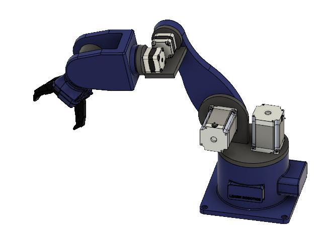
When you’re finished, attach two NEMA 23 motors to link 1 (motor mount) and two NEMA 17 motors to link 3. Use rigid joints for the motor attachments. Here’s what the assembly should look like with everything completed!
Finally, add some screws to the motor mount holes. This will make the assembly look more realistic. Plus, these components will be added to the Bill of Materials (BOM) when we generate a drawing.
Add Fasteners in Fusion 360
Fusion 360 has a built-in McMaster-Carr utility that allows you to easily search and add fasteners to your models. While you can always import a 3D model of a specific bolt or part, I wanted to show you how to add parts directly from the McMaster-Carr tool.
First, navigate to the Toolbar and select Insert > Insert McMaster-Carr Component. Then, follow along with the steps below:
- Click on Fasteners, Screws & Bolts.
- Then, select Metric under “System of Measurement.”
- Choose “Rounded Head Screws.”
- From the menu on the left, find the “M4” thread size.
- Narrow down the search by clicking “Phillips Rounded Head Screws.”
- Next, pick “Metric 18-8 Stainless Steel Pan Head Phillips Screws.”
- Choose “Black Oxide” then scroll down to the 8 mm long screws and click on the part number in the table.
- Select Product Detail.
- Scroll down to the 3D model and choose “3D STEP.”
- Press SAVE to insert the CAD model into the current design.
Now you can use these steps to search through the McMaster-Carr catalog and add custom fasteners and components to your designs.
Once you have all the fasteners added to your model, it’s time to create a drawing of the 3D robot arm.
Generate a Drawing using Fusion
Now that we have our assembly, it’s time to generate the epitome of all CAD drawings: the Exploded View!
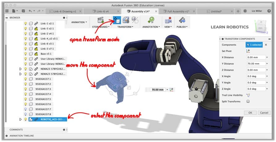
First, switch to the Animation workspace. Then follow along with the following steps:
- Click on Transform in the Toolbar.
- Select a component and move it slightly in one direction.
- Repeat this process for the remaining components.
I recommend starting at the end-effector and working your way back to the base. That way everything will be nicely lined up for this exploded view.
Once you’re finished, go to File > New Drawing > From Design. This will open up a menu. Make sure the full assembly is selected and you have the appropriate page size. Then, press OK.
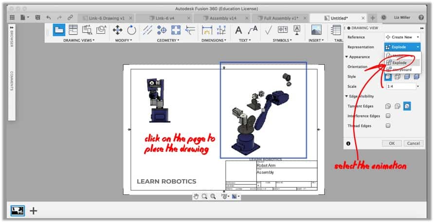
A new tab will open up with the drawing view. Click anywhere on the drawing to place your model.
Now, let’s add the exploded view. Go to the Toolbar and click “Place Base View.” In the Drawing View Panel, select “Exploded View,” under the Representation option.
Adjust the Orientation, Style, and Scale to your liking. Then click on the drawing to place the model.
Add a Bill of Materials (BOM) to your drawing
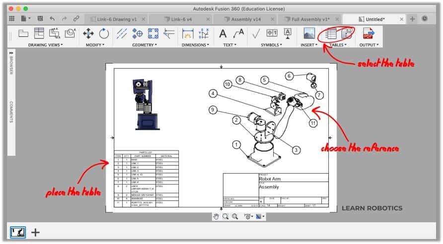
Once you have all the views placed, you can add a Bill of Materials (BOM) to the drawing. This will call out each of the components in a view and generate a nicely formatted table.
Go to the Toolbar and Click Tables > Table. Select a view to add the callout bubbles. A table will appear. Click the bottom left corner of the drawing to place the table. Reposition views if the table overlaps.
Lastly, adjust the information in the Title Block. Double-click on the Title Block and edit the Project, Title, and associated fields. When you’re finished, your drawing is ready to export.
Go to the Toolbar and click on Output > Output PDF. You can also export this drawing as a DWG or CSV file. Check “Open PDF,” then click OK in the Output PDF menu. The PDF will automatically open once it’s generated.
And that’s a wrap!
You can 3D print from Fusion 360
Over the last four tutorials, you learned how to design a robot base, draft a motor mount, import components, create a full assembly, and export drawing files. In the final tutorial, I’m going to show you how to prep your files for 3D printing.
Download the Starter Code Files
As always, give this post a share on whatever Social Media platform floats your boat! It helps the blog grow and supports me in my mission of helping 1 Million people Learn Robotics.