

Fusion 360 for Robotics Tutorial Series
- Part 1: Create a Robot Base in Fusion 360
- Part 2: Draw the Motor Mount in Fusion 360
- Part 3: Convert Bodies to Components for Assembly — You are Here
- Part 4: Add Joints in Fusion 360
- Part 5: Generate Drawings, STLs, and G-code using Fusion 360
In the previous Fusion 360 tutorials, we learned how to draw two components for our robot arm: a robot base and a Nema23 motor mount. In this tutorial, I’m going to teach you how to use drawings to create models in Fusion 360.
Rather than walk through each component step-by-step, I wanted to show you 1) which components are left to draw; and 2) how to use these drawings to develop parts.
Practice makes perfect, so I highly recommend drawing these components by hand rather than importing them into Fusion 360.
Let’s jump into it!
How to use Fusion 360 Drawings
Engineers use drawings to document the features of a part. In this section, you’ll learn two ways you can use drawings to create a component
Draft Components Manually
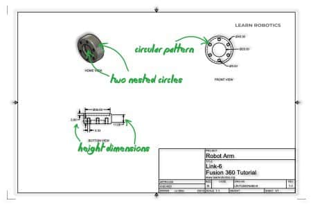
The first way you can use a drawing is to create a 3D model by hand. Gather a PDF copy of the drawing and look for features, dimensions, and notes. I’ve annotated some of the important parts of this drawing with a green marker.
Then, create a new design in Fusion 360, and start drafting the model. This method usually takes the longest, and there is a possibility that your model won’t be the same as the original author’s.
However, if you’re new to drafting, this method will help you practice. I recommend looking at the drawing from all planes and try to decompose the 3D model into 2D shapes. Then use the listed dimensions to develop your part.
If by chance you were lucky to have a CAD file (STL, STEP, etc), then you can import this file into Fusion 360. In the next section, I’ll show you how to use a CAD file in your designs.
Import existing CAD Files in Fusion 360
One of the easier (and probably most preferred) methods of creating models is to find the original drawing or CAD file and import it into Fusion 360. This will ensure that you have the most accurate representation of the part from the original author.
Since we’re working on a 3D robot arm, I’ve put together drawings for the remaining links. Feel free to download the component drawings below!
Download the Starter Code Files

Now, let’s learn how to use these drawings to import new parts.
First, go to File > Open > Open from my computer… Then, select the file you want to import.
Once the file has been added and uploaded, it’s ready to use. If you opened up a drawing file, go to the left browser and right-click on the body you want to use. Then select open.
That’s all to importing a file or drawing in Fusion 360! Pretty nifty, right?
Draw the remaining components
Before jumping to the next tutorial, make sure you’ve drawn all of the bodies and converted them to components.
Convert a Body to a Component in Fusion 360
Fusion 360 has two different concepts in modeling: body and component. Because we want to create a robot model with joints, we will have to convert each body into a component.
According to Autodesk, a component is “a position and motion-independent part of an assembly within our single design environment.” In the next tutorial, we’ll use joints to define relationships between other components. This will ensure that our design is mechanically accurate.
Here’s a quick way to convert bodies into components.
- Right-click on the body and select “Convert to Component.
- You’ll see another item appear in the Browser.
- Double-click on the new Component and type in a meaningful name.
- Repeat this process for each Body in the design.
In the next Fusion 360 tutorial, we’re going to look at creating assemblies with these components. Finally, we’ll generate drawings and prepare the components for 3D printing.
Download Autodesk Fusion 360
Did you know you can follow along with these tutorials using Fusion 360? If you haven’t already, check out the free download of Fusion 360. You have no excuse not to try out this tutorial and start gaining skills in robotics and CAD modeling.
Like this tutorial? Be sure to share it with a friend!


2 Responses
Hi,
The tutorial is great, but I am not getting the downloads to unlock by subscribing. Is there another way to access them?
Hey Wendy, the links should be working now. You can also click here to access them. ~Liz