Fusion 360 for Robotics Tutorial Series
- Part 1: Create a Robot Base in Fusion 360
- Part 2: Draw the Motor Mount in Fusion 360 — You are Here
- Part 3: Convert Bodies to Components for Assembly
- Part 4: Add Joints in Fusion 360
- Part 5: Generate Drawings, STLs, and G-code using Fusion 360
In the last Fusion 360 tutorial for beginners, you learned how to create a robot base by drawing, combining, and extruding a square, circle, and rectangle. In this tutorial, we’re going to expand on this skill set by creating a motor mount. This component will attach to the base and the arm link for our robot arm.
First, create a New Design and ensure that your units are in millimeters. Then, create a sketch on the top plane. Draw a 100 mm center diameter circle and extrude it up 10 mm.
Next, draw a 95 mm center diameter circle on the bottom plane and extrude it out 3 mm. This component will sit snuggly into the base, so if you’re using custom dimensions, make sure your base matches your motor mounts.
Now, we’re ready to draw the motor mount. Switch to the front plane and draw a rectangle 80 mm by 50 mm.
You can customize this shape by adding a curve with a radius of 45 mm. Extrude this plate out 10 mm, symmetrically, and make sure you set the extrusion to “join” (not cut).
Download the Fusion 360 Tutorial Starter Code Files
That’s it for this part of the Fusion 360 Tutorial on how to build a robot arm. Be sure to pick up a copy of the Starter Project files and the full Starter Code Files below.

Add Holes in Fusion 360
Follow along with the tutorial video, or read on for the step-by-step instructions.
We’ll be using Nema23 motors for the base, so let’s draw some mounting holes. Create a 47.244 mm square on the face of the motor mount plate. Then press “H” to bring up the hole menu.
Draw your holes using the “From Sketch” command. Then, place your holes at the corners of the square.
Lastly, we’ll create the axle hole by using the center point from the previous sketch. Repeat the process of drawing a 6 mm axle hole using the hole tool.
Once you have that complete, it’s time to create the motor mount on the top plane. Repeat the steps for drawing a 47.244 mm square on the top plane and using this as a guide in the hole tool.
[amazon box=”B079V4PXYD” template=”list”]Adjust positions in a Fusion 360 Sketch
Sometimes when you’re sketching, your dimensions won’t line up correctly and you’ll have undesirable overlaps between parts.
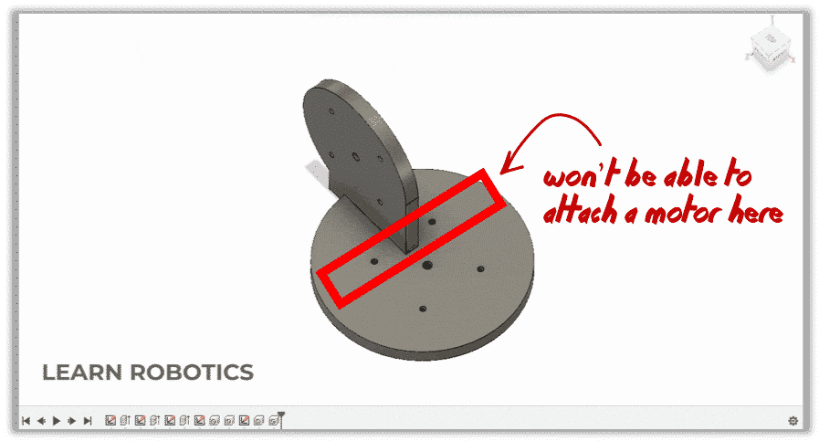
For example, you’ll notice that some of the motor holes on the top plane are running into the vertical bracket. Therefore, the motor won’t properly fit into this component.
In this section, I’m going to teach you how to adjust the position and re-align sketches in your Fusion 360 design.
Rather than erasing everything and starting over, you can use the Fusion 360 Timeline to backtrack to the correct sketch.
Revert back to the sketch in the timeline, then right-click on that block and select “Edit Sketch.” I like to use dimensions to fix this problem. Double-click the dimension you want to change, and type in a new value. Repeat this process until you’ve fixed the overlap problem.
When you’re finished, go to “Stop Sketch” in the menu. Then, press the fast-forward arrow to go back to the current state of the design. Your changes will populate through the remaining actions, and you should see the corrected part.
Download the Fusion 360 Tutorial Starter Code Files
That’s it for this part of the Fusion 360 Tutorial on how to build a robot arm. Be sure to pick up a copy of the Starter Project files and the full Starter Code Files below.
In the next tutorial, we will sketch the remaining parts of our Industrial Robot Arm. You’ll also learn how to generate drawings with dimensions using Fusion 360.
Lastly, be sure to share this article with a friend who wants to improve their Fusion 360 modeling skills.