

In this tutorial I will show you how to use an OLED Display with Arduino. There are several types of displays available in the market, namely: LCD (Liquid Crystal Display), LED, OLED (Organic LED) and eInk display. LCD and OLED are the most common ones. In this post we will learn how to use OLED display with Arduino. Let’s begin.
Materials for this Project
To create this project, you’ll need the following materials:
- Arduino: We’ll use this controller as the brain of the project. I used the Arduino UNO but feel free to use whichever Arduino board you like (Mega, Nano or Micro). Just make sure you know the Pin mapping of your board.
- OLED Display: There are different types of OLED displays. The one I have used is 1.3″ I2C module. It has a resolution of 128 x 64 and works with the SH1106 Driver.
- Proper driver for the display: I used the SH1106 driver, so I installed the Adafruit_SH1106 library for that. Make sure you check what driver your display needs. It should be mentioned in the description of product on the website.
Understanding I2C Protocol:
As our display module uses I2C interface for communication, We must first understand the I2C Protocol.
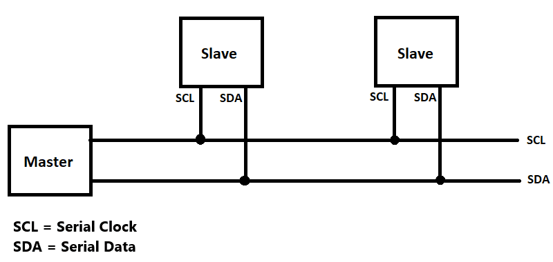
I2C is a communication method which only uses 4 pins. In this Protocol, multiple Masters (Microcontrollers) can be connected to multiple slaves (Sensors) using 4 pins: VCC, GND, SDA and SCL.
In I2C data is transferred in form of packets. These packets contain frames of data.
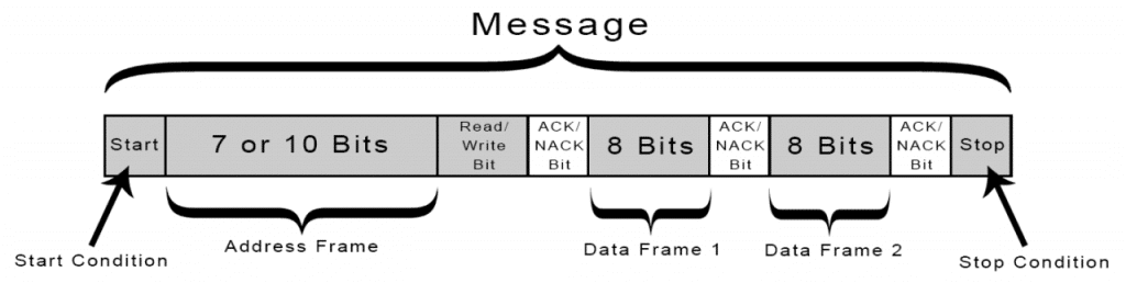 First frame contains a “Start Condition”, when a device reads the start frame it gets ready for incoming data. Next frame contains the address of the device. Then there are two data frames which contain the instructions. Finally the Stop condition indicates the end of the packet.
The Ack/Nack Bits are the acknowledge bits , when set of data is received successfully acknowledge bit is sent. This was a short explanation of I2C, for in depth information refer I2C Wiki.
OLED Arduino Wiring Diagram
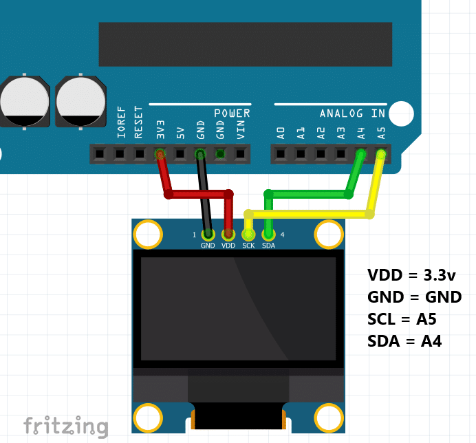
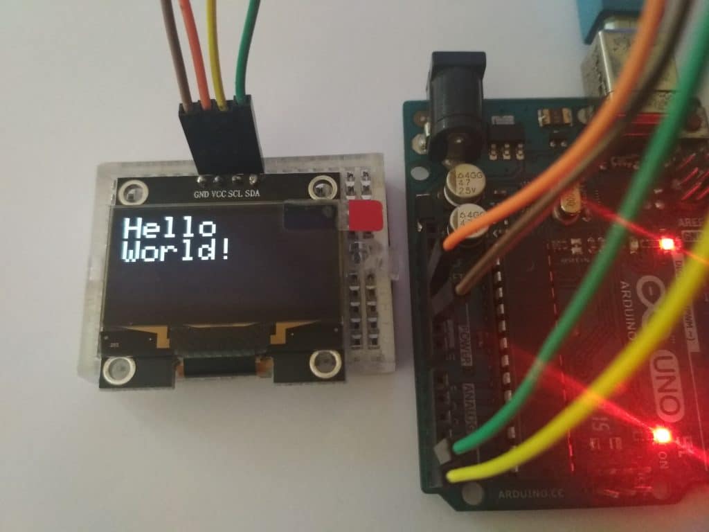
Connections are very simple, just follow the diagram and you’re done. OLED displays are very power efficient and works perfect on 3v. After the connections are made, it’s time to upload the test code.
Program OLED Display with Arduino
Before we can upload the code, there are a couple of libraries that needs to be installed. Below I have listed the libraries needed:
- Wire.h
- Adafruit_SH1106.h
The Wire.h library must be already installed in IDE, Download the SH1106 library from here.
Click “Clone or Download” on the right. Then choose “Download ZIP.” Extract the Zip file and copy it into Arduino >> Libraries.
Then , create a new sketch, and write the code given below:
#include <Wire.h>
#include <Adafruit_SH1106.h>

#define OLED_RESET 4
Adafruit_SH1106 display(OLED_RESET);

void setup()
{
  Serial.begin(9600);
  display.begin(SH1106_SWITCHCAPVCC, 0x3C);

  display.display();
  delay(2000);
  display.clearDisplay();
}

void loop()
{
  display.setTextSize(2);
  display.setTextColor(WHITE);
  display.setCursor(0,0);
  display.println("Hello");
  display.setTextSize(2);
  display.setTextColor(WHITE);
  display.println("World!");
  display.display();
  delay(2000);
}
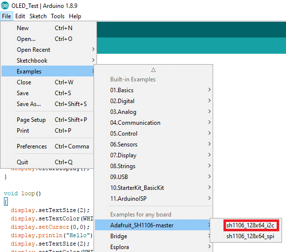
Upload the code to the Arduino, and you should see a “Hello World!” message on the screen. You can also try the example code present in Arduino IDE.
Goto File >> Examples >> Adafruit_SH1106-Master >> sh1106_128x64_i2c
Upload the example code to see some cool animations.
Final Note
With that complete, now you can use the OLED display for your projects. These displays can be very useful for projects such as a weather station, robot display, or electronic dice. The possibilities are endless once you learn the basic configuration.
If you enjoyed this tutorial, consider buying a copy of my Mini WIFI robot eBook. I show you how to design, build, and program your very own custom robot that can be controlled over WIFI. Pick up your copy, today!


4 Responses
Good Day Liz
My Name is Gavin – I started a project but being a bit further on with age i am battling to learn and follow some of the tutorials. I am looking to build / design / create a HUD unit with the MPU-9250 but well having problems getting to display the information to the OLED unit Well i can get the unit to display all the examples and i can get the MPU-9250 to print out the info on the Serial Monitor but i am loosing it trying to get the info to display on the OLED.
Hi Gavin, Thanks for dropping by. Without seeing your code and setup, it’s a bit tough for me to debug what the issue is. If you’re able to pull data from the MPU, I recommend storing it into a variable. Then you can use the variable to “print” it to the OLED. There are steps on how to do this above. If it’s not a software issue, it could be a wiring issue, so double check your connections. If you need more help, feel free to schedule a quick call with me and we can troubleshoot further. Good luck! ~Liz from Learn Robotics
I liked and Wana practical on it.
Awesome!! Can’t wait to see your project 🙂