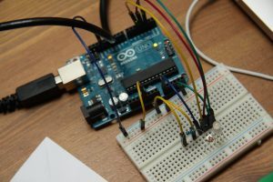
Welcome back to another LR tutorial! In this article, I will show you how to configure your Arduino LCD using Sensor Shield V5. Set aside 30-45 minutes, and you’ll be well on your way to displaying data from your Arduino or Sensors.
In my Youth Robotics classes, we use Arduino Mobile Robots. I wanted to include an LCD so that there was an easy way to display sensor data and information without having to be tethered to a computer. Whether you’re using a robot or not, this tutorial will help you set up your Arduino LCD using a Sensor Shield.
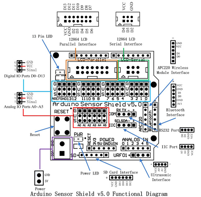
Start by gathering the wiring diagrams and pinout maps for each of your components. For this project, I used the Sensor Shield V5 model and a 16×2 LCD. Both of these diagrams can be seen below.
Step 1 – Connect the Arduino Sensor Shield and the LCD module.
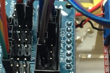
We will use the LCD Parallel Interface to make our connections from the LCD module to the Arduino.
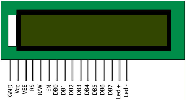
I found this very helpful diagram of wiring your LCD to an Arduino Uno. We will use this information to translate the wiring to the Sensor Shield (rather than directly to the pins on the Arduino Uno).
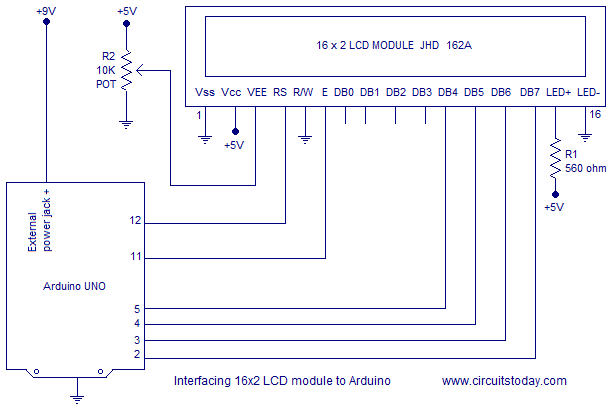
Here’s a chart of your connections. I recommend either printing out these diagrams or copying down this table while you’re plugging things in.
| LCD Pin # | Name of Pin on LCD | Location on Sensor Shield |
|---|---|---|
| 1 | Vss | GND |
| 2 | Vcc | +5V |
| 3 | Vee | 10K Pot (Signal) * |
| 4 | Rs | D12 |
| 5 | R/W | GND |
| 6 | E | D11 |
| 7 | DB0 | EMPTY |
| 8 | DB1 | EMPTY |
| 9 | DB2 | EMPTY |
| 10 | DB3 | EMPTY |
| 11 | DB4 | D5 |
| 12 | DB5 | D4 |
| 13 | DB6 | D3 |
| 14 | DB7 | D2 |
| 15 | LED + | 220 ohm resistor to +5Vcc |
| 16 | LED – | GND |
For items listed in the “Location on the Sensor Shield” column, you’ll use the digital pins on the LCD Parallel Interface which is shown in Orange on the Sensor Shield diagram above.
I recommend plugging your jumper cables into the LCD first (you’ll need 12 of them), then writing the color of the wire next to each connection. This will make it easier when you’re trying to figure out where the wires go. For the second set of Vcc and GND for the LED, you can use any available V or G pin on the Sensor Shield.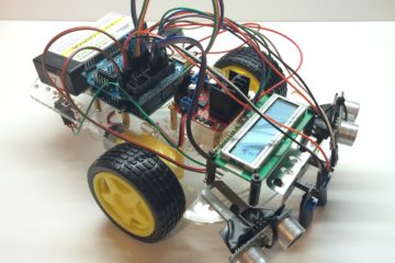
* The potentiometer is used to control Contrast on the LCD. We’ll wire that up in this section. First, connect a 10K potentiometer to pin 3 on the LCD. Using the potentiometer, attach the left leg to ground, middle leg to to Pin 3 on the Sensor Shield, and right leg to 5V. Rotate the potentiometer knob to make the screen brighter or darker.
Step 2 – Configure the Software
You’ll set up your sketch the same way you would for any other Arduino device. I won’t go into detail on how to write an Arduino program in this article, but if you need a refresher, you can check out my post, Simple Guide to Writing an Arduino Program.
 Liquid Crystal Library
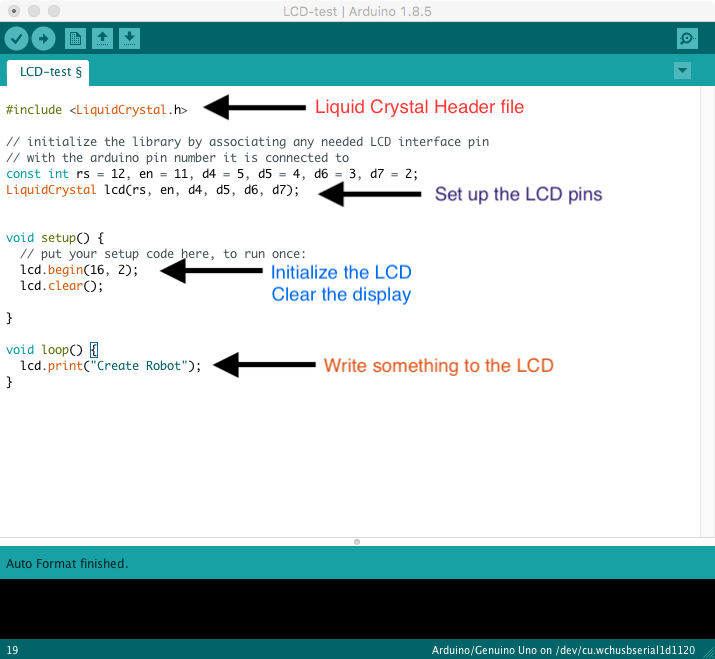
We will use the LiquidCrystal library in order to write data to our LCD. This library is standard with every copy of the Arduino IDE. To set it up, include the Liquid Crystal header file at the top of your sketch.
Important Commands
A couple important commands you’ll need when you’re sending data to the LCD:
Begin:
Initialize the LCD in the setup() method.
lcd.begin(16,2); //setup the 16 segment, 2 row display
Clear:
Clear the LCD
lcd.clear(); //clears every position in the LCD
Set Cursor:
Sets the starting position of the cursor.
lcd.setCursor(column, row); //starts your message a position column, row
Think of the LCD as a grid of 16 columns and 2 rows. Each position in the grid is similar to a coordinate in an (x,y) plane. So if you want to write values to the first row, 2nd position, you’d set the cursor to (2,0). Note: we start counting at 0.
Print:
Writes the message to the display
lcd.write("text here"); //will write "text here" on the display
You can also write values from sensors using variables. Replace “text here” with the variable name or sensor reading to write it to the LCD.
Step 3 – Display sensor data on the LCD
For the Arduino Robot, I wanted to display a “Welcome Message” followed by Infrared (IR) Sensor readings on the LCD.
First, I set up the pins for the IR sensors using some global variables.
int lir = A0;
int rir = A5;
In the setup routine, configure the IR sensors as INPUTS.
pinMode(lir, INPUT);
pinMode(rir, INPUT);
Then flash a quick Welcome Message on the display for 2 seconds.
lcd.print("Welcome Create");
delay(2000);
lcd.clear();
Next, I created a method to display IR sensors. Enter your email to gain access to this code (it’s FREE)!
[pretty-locker id=”339508″]void displayIR(){
int left = analogRead(lir); //get readings from Left IR
int right = analogRead(rir); //get readings from Right IR
lcd.setCursor(0,0); //first row
lcd.print("IR Sensor Data"); //print message
lcd.setCursor(0,1); //second row
lcd.print("L: "); //print message
lcd.setCursor(3,1); //set cursor to column 3, row 2
lcd.print(left); //print the left sensor reading
lcd.setCursor(8,1); //set cursor to column 8, row 2
lcd.print("R: "); //print message
lcd.setCursor(11,1); //set cursor to column 11, row 2
lcd.print(right); //print right sensor reading
delay(150); //give enough time to show the readings
lcd.clear(); //then clear the screen to remove previous data
}
Lastly, I called the displayIR() in the loop() method.
void loop() {
  displayIR();
}
Remember, only the code called in loop() is executed on the board.
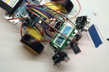
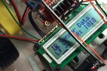
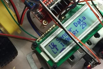
When you’re done writing the code, be sure to compile and upload it to your Arduino. You can see the results that I got when I was finished with this project. The left picture shows the left sensor on white and the right sensor on black. The right picture shows the opposite.
Project Wrap Up
In summary, connecting an LCD to an Arduino Sensor Shield V5 is not that complicated. Just make sure you connect the pins from the LCD to the correct pins on the Arduino Sensor Shield.
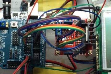
In this example, I made use of the LCD Parallel Pins on the top left part of the shield. I then programmed the board using the Liquid Crystal library. Lastly, I connected some IR sensors to collect data from the environment to show on the display.
If you enjoyed this tutorial, I invite you to check out my beginner robotics course. It walks through the full building, wiring, and programming of mobile robots. Enroll here and gain access to 20+ hours of content, projects, quizzes, and Course Certificate.