I’ve been doing a lot of circuit work these days and wanted to share with you my methodology for surface mount soldering.
This tutorial is meant to show you how to surface mount solder in three steps. It’s the guide I wish I had to outline the process of going from IC in its raw state to an IC I could use in a prototype or on a breadboard.
But first, what is surface mount soldering?
Surface mount (SMT) soldering is the process of attaching a component to the face of a circuit board. You can buy various IC’s, LED’s, resistors, and other components with SMT packages. Each component has a footprint or layout that they can be attached to a circuit board. The footprint is typically listed in the manufacturer’s data sheet.
Once you have the footprint, purchase the same style breakout board. The breakout board allows you to use the IC or component on a breadboard for prototyping.
It’s important that you have the same size footprint on the breakout board as the component because you’ll use the pads to apply the solder.
Now, let’s get started!
Prepare your Workspace
The first thing to do is prepare your workspace. I recommend clearing off a desk or table and giving yourself plenty of room to work. Soldering in a cluttered environment is more difficult than soldering in a clean space.
You’ll also need some materials to get started. Check out the list below for all the tools I recommend.
- Helping Hands
- Magnifying Glass and Helping Hands
- Adequate lighting
- Tweezers
- Soldering Iron (I don’t recommend going cheap on this.)
- Soldering Iron holder
- Wet Sponge
- Solder
- Solder wick
- Solder sucker
- Multimeter
- Optional all-in-one combo stand
If you’re also planning to solder through-hole components (THT), I recommend a set of wire cutters and wire strippers. Lastly, gather the components you want to solder.
Once you have everything within arms reach, it’s time to heat up your soldering iron. I set mine around 375 °F. If you find that the iron is too hot, you can always turn it down.
While the iron is heating up, go get yourself a wet sponge. Regular tap water is fine in most cases. It’s important to clean the soldering iron tip frequently. The goal is to have a clean, shiny tip each time you are connecting parts. On the other hand, if you neglect to clean the tip, you’ll risk corrosion and ruining the tip entirely.
Now, you’re ready to start soldering.
Surface Mount Solder the Breakout Board
Clip the breakout board to your helping hands. Then, adjust the magnifying glass so that the solder pads are visible and clear to see. This might take a few minutes to get right, but it makes soldering easier, so take your time with alignment.
It’s also helpful to have the board parallel to the magnifying glass and resting against the table. That way you’re not soldering against the helping hands, but rather against a solid surface.
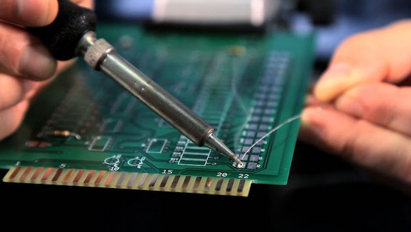
Take the soldering iron and heat up the pads for the component you’re trying to attach.Apply a small amount of solder. (Emphasis on small.) Because the components are usually very small, you don’t want to apply too much solder and join adjacent pads.
Don’t forget to Breathe!
A technique I like to use is applying solder on the exhale. Take a breath in and then when you exhale, solder the pad simultaneously. Repeat this process for all the pins on your component. I recommend only doing one component at a time.
Once the pads have a small amount of solder on them, carefully grab the chip with your tweezers. These chips are small, so be careful not to lose it or drop it while transferring out of the strip.
Use the tweezers to align the component pins with the soldered pads. This will take a bit of patience, but it’s critical that the component is lined up properly on the board.
After the pins are lined up, in one hand, use the tweezers to hold down the base of the chip. Take your soldering iron in the other hand, and heat up one of the pins. The goal is to reflow the solder and connect the component’s leg to the board.
Be sure the component lies flat while you’re soldering. You don’t want part of the chip mounted at an angle. Tweezers make it really easy to press the chip down.
Repeat this process for the remaining legs. Try not to bridge any of the legs together. You can also apply a little more solder if you think the pin needs more.
Now you’re ready to verify that the component has been placed properly.
Verify Your Solder Joints
I like to take a multimeter and test each of the legs and pads for conductivity. The purpose is to make sure that the pads are connected to the pins and the neighboring pins are not connected. You can do this by flipping the multimeter setting to the sound option.
Then take your test leads and connect them together. You should hear a beep or buzzing noise. If you touch one probe to the pad and the other end to the pin on the chip, you should hear a noise from the meter. (That’s good and what you want.)
However, if you touch one lead to one pin and one lead to another pin and hear a noise, then you’ve bridged two pins (not good). Unless these neighboring pins have the same signal, you’ve crossed signals with your soldering. To “undo” this you can use a solder sucker or some solder wick. I think the latter is a better option for these very small components.
Desolder Bridged Pins
If you inadvertently use too much solder, you can bridge neighboring pins. In this case, you’ll need to desolder those pins, and try soldering them again.
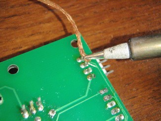
First, take a small piece of solder wick and hold it against the join that needs to be desoldered. Apply the tip of the soldering iron to the wick. As the solder melts, it will be drawn onto the solder wick and away from the joint. Now you have a clean slate to work with and can try re-soldering those pins.
Subsequently, you can repeat this process for any additional surface mount components on your breakout board.
Once you have all the surface mounted components complete, solder any through-hole (THT) components such as header pins, screw terminal blocks, wires, LED’s, buttons, etc.
Through-hole soldering is similar to surface mount soldering, but it’s much easier because the components are bigger. Connect the component to the board by placing it through the hole.
Then, flip the board over and heat the solder pad with an iron. Apply a small amount of solder to the heated pad. Let the solder flow, then remove the soldering iron. The component should be secure to the board. Snip any excess leads from the component. You don’t want these sticking off the board!
For header pins, I recommend connecting them into a breadboard and laying the breakout board over the top. The breadboard will hold the header pins while you’re soldering and keep everything flush.
Wrap Up & Final Thoughts
Surface mount (SMT) soldering is a great skill for anyone interested in building electronic prototypes. It’s not very difficult to learn, however, it requires the right tools and a lot of patience to do correctly.
In addition to surface mount soldering with an iron, you can also perform a “paste and bake” method which uses solder paste and a heating element. I don’t talk about this methodology in this tutorial, but it’s definitely an alternative methodology if you’re looking to do a lot of SMT components on a single board.
Lastly, I highly recommend looking into building your own PCB’s in a software like Eagle or KiCad. If you have 3+ boards to build, surface mount soldering becomes very time consuming. It’s almost not worth doing by hand. Instead, draw the circuits electronically, and send them off to be printed.
Have a question? Be sure to drop them in the comments section below. Also, let me know whether or not you’d like to learn more about how to build your own custom PCB’s from scratch!