

You probably landed on this page because you’re interested in programming a PLC (programmable logic controller), but have no clue where to begin. Welcome! This article is designed to give you a primer in PLC Programming Basics for Industrial applications.
At the end of this article, you will have familiarity with reading Ladder Logic (also known as Ladder Diagrams) so that you can work on projects using PLCs. In future tutorials, I will show you how to practice writing Ladder Logic for common Industrial Control Systems.
One thing to note, is there are four additional industrial programming languages you can learn. In my experience, Ladder Logic is the most popular followed by Structured Text and Function Block. You can read more about the IEC61131-3 languages here.
So, without further ado, here’s my spin on PLC Programming Basics using Ladder Logic.
How PLC Programs are Executed
Before we can dive into the programming aspect of PLCs, it’s important to understand how the PLC works. When a PLC executes a program, it must know, in real-time, when external devices controlling a process are changing. During the Program Scan Cycle, the PLC reads the inputs, solves the Ladder Logic, and energizes (or de-energizes) outputs. Because inputs can change at any time, this process repeats over and over again while the PLC is in RUN mode. The diagram below shows a model of the PLC Program Scan Cycle.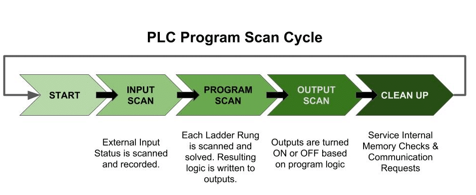
Scan times can vary from 1 millisecond to 20 milliseconds. This is important because if the controller has to react to an input event faster than the scan time, it may never detect the change. Scan time is influenced by a few factors including the processor module speed, length of the ladder program, type of instructions executed, and the actual true/false conditions.
I also want to point out that the ladder programs we’ll be looking at are very simplistic. Therefore, we don’t have to worry so much about scan times. It’s just something to be aware of if you’re working with larger-scale systems.
Now that we have a general overview of how the PLC executes the program scan cycle, we can talk about ladder logic fundamentals.
Ladder Logic Fundamentals (How to read and write Ladder Diagrams)
Programs in Ladder Logic are written differently than embedded or flow-chart programming. Ladder Logic is a rule-based language, meaning the conditions must be met for the output to be energized. When I was first learning ladder logic, I had a hard time wrapping my brain around the symbology. Ladder Logic is very easy to understand once you get the hang of a few basic principles.
1. Rungs are Read Left to Right and Top to Bottom
There are two rails (left and right) and they are connected by rungs. This builds out a program that looks like a ladder. Ladder rungs are read starting from the left to the right and then sequentially, top to bottom.
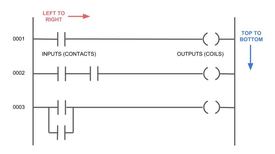
2. Inputs or CONTACTS are on the left. Outputs or COILS are on the right.
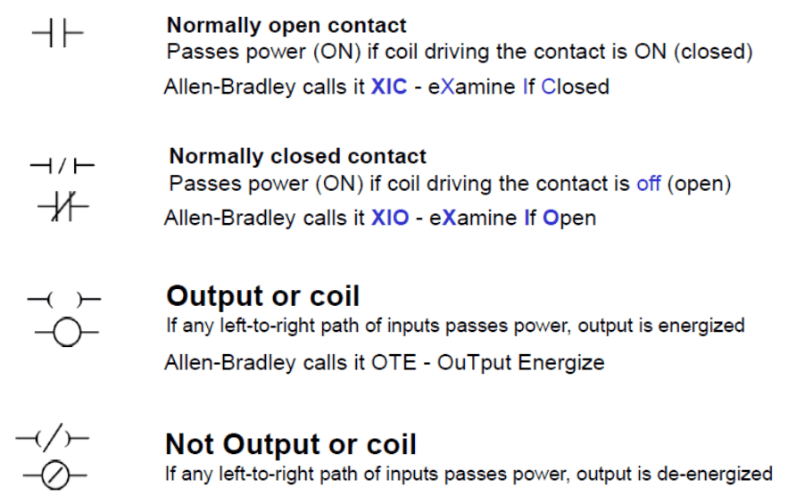
You’ll notice a few basic symbols in the ladder program, above. Common symbols are called “Normally Open”, “Normally Closed” and “Output.” Check out the chart below. I learned on Allen Bradley PLCs, so I’ll refer to the XIC / XIO / OTE combination. Just know that these names are interchangeable and synonymous.
3. Combine symbols to create a logical flow.
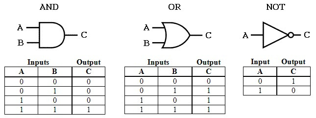
Ladder logic is based on principles from digital logic gates. There are three basic types of digital logic gates: the AND Gate, the OR Gate, and the NOT Gate. View the Truth Tables, below.
Logical AND condition
When you combine inputs and a bit of digital logic, you can create the status for your output. Here’s an example of the AND condition written in Ladder Logic.
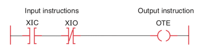
There are two inputs: XIC, XIO, and an OTE. This rung is read: If XIC and XIO then OTE. Both the XIC and the XIO must be active for the OTE to be energized. You can substitute “if-statements” into the rung to understand the condition. Most PLCs make it easy to figure out what is ON by highlighting the active elements.
Demonstrating the OR condition
We can create the OR condition by using a branch. You’ll see in the video below, the Start Button and the Motor are on separate branches. This is a common pattern for motor starters.
First, the program will check to see if the Start button or the motor is ON and the stop button is OFF, energize the motor. Here’s a demonstration.
This configuration is called “latching the motor.” Once the motor is on, there’s always a path for it to stay on, so long as the stop button isn’t pressed.
Now that you’ve seen the most common symbols and configurations in ladder logic, it’s time to practice your skills. In my opinion, the best way to practice is to “do.” So, here are some resources to get you programming PLCs.
PLC Programming Simulation Software
There are a couple of routes you can go with practicing your PLC programming: program in simulation, program real hardware, or read controls engineering books. I’ll cover all three of these options in this section.
I think learning on simulators is one of the better approaches to PLC programming. Real hardware can be expensive and dangerous to test, so working in simulation allows you to practice your skills while eliminating the hazard and cost barriers.
Also, these options only run on Windows Computers (as most Industrial Controls programs do). You can run some of the simulators in a Windows VM, but be mindful of RAM, 3D graphics, and acceleration. Programs like FactoryIO can be graphic-intensive and laggy on some VMs.
Here are a couple of simulators I’ve used that can help you learn PLC programming for free or low-cost.
CoDeSys
The first simulator option is CoDeSys (pronounced CO-da-SYS). CoDeSys is a pretty popular freemium control software that many international folks use. The IDE has a bit of a learning curve, but it includes an HMI program and Simulator, so you can create, model, and test projects as you desire. It also interfaces with Raspberry Pi, so if you wanted to incorporate some hardware and sensors, you can do that pretty easily. Here’s a project I wrote in Structured Text to model traffic lights.
RSLogix 500 Emulate
Learn Allen Bradley hardware using RSLogix 500 and the emulator. To get this working, follow the instructions listed here.
If you’re interested in becoming more versed in Allen Bradley, I recommend checking out this Udemy Course by Paul Lynn (aff. link – save $5). I took this course, and it’s a very comprehensive walk-through if you’re looking to go the A-B route.
As an aside, I will say, that nobody (I know) uses RSLogix 500. Usually, plants have upgraded to RSLogix 5000 or Studio 5000. This is especially true if they’re programming ControlLogix or CompactLogix controllers. With that said, the programming IDE is a bit different, but the fundamentals translate over pretty well.
FactoryIO with or without Add-ons
Lastly, there’s another simulator called FactoryIO, that can simulate an entire automated work cell. I think this is the coolest of all the options. The software ranges in price from $40 to $800, depending on which option you pick.
If you own a PLC, you can interface it with the software to build a working prototype. There’s also a Udemy course you can enroll in to get you started with Factory automation using FactoryIO.
Rather than use a simulator, you can also opt to use real hardware to practice your PLC programming skills.
Learn PLCs by Working with Real Hardware
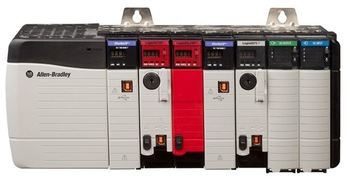
There’s nothing like gaining experience working on real hardware. You can grow your skills tremendously by working in an automation lab on real PLCs. If you have a choice of which PLC to learn, I recommend staying with industry standards: Allen Bradley Logix, Siemens S7, Mitsubishi Electric, and OMRON.
If you’re just looking to build some projects in a Hobby (or economic) capacity, I recommend checking out CLICK PLCs or Allen Bradley’s Micro820 series. The Micro820’s are nice because the software, Connected Components Workbench (CCW), is free and supports both logic and HMI development. Plus, A-B is a recognized brand, so you’d still learn some transferrable skills. Once you choose which PLC platform you want to work with, it’s time to wire up some sensors, and get your automation projects rolling!
Read Controls & PLC Books
Lastly, you can read some controls and PLC books to gain basic PLC programming skills. A lot of PLC programming is “seeing” and “repeating” examples that work. There’s no reason to reinvent the wheel if someone else has already figured out a way of doing something. This is especially true with controls engineering.
Here’s a list of some of my favorite Controls and PLC books.
[amazon box=”1631269321,1260031101,1784396036,1284119424,1631269410″ template=”list”]Recap of PLC Programming Basics
All and all, PLC programming is pretty simplistic compared to more embedded control languages. If you have a background in digital logic gates and understand the “if-statement,” you can learn Ladder Logic in a matter of a couple of hours.
As with anything, it’s important to practice programming ladder logic if you want to get better at it. This article was designed as a primer for more complex industrial automation controls. If you enjoyed this type of content, please drop a comment below, and let me know your thoughts. You can also follow Learn Robotics on Facebook and Instagram to see what we’re up to behind-the-scenes.
Related Articles:


10 Responses
Too bad your example is incorrect.
This rung is read: If XIC and XIO then OTE. Both the XIC and the XIO must be active for the OTE to be energized.
It should be: If XIC and NOT XIO then OTE according to the circuit diagram.
Mark,
XIC is an examine if closed symbol
XIO is an examine if opened symbol.
Both of these conditions must be active for the rung to be true in an AND condition. If it’s true, then OTE will be energized.
Usually, when you’re connected an online with a controller, you’ll see these bits light up and can troubleshoot whether or not the OTE is energized based on the logic.