

If you’re anything like me, then you enjoy building mobile robots. As I’m sure you’re aware, mobile robots are comprised of 5 parts: chassis, motors, controllers, sensors, and power. To cover three of these groups, you’ll need to properly wire the motors to the controllers (motor and master) and then add your power supply.
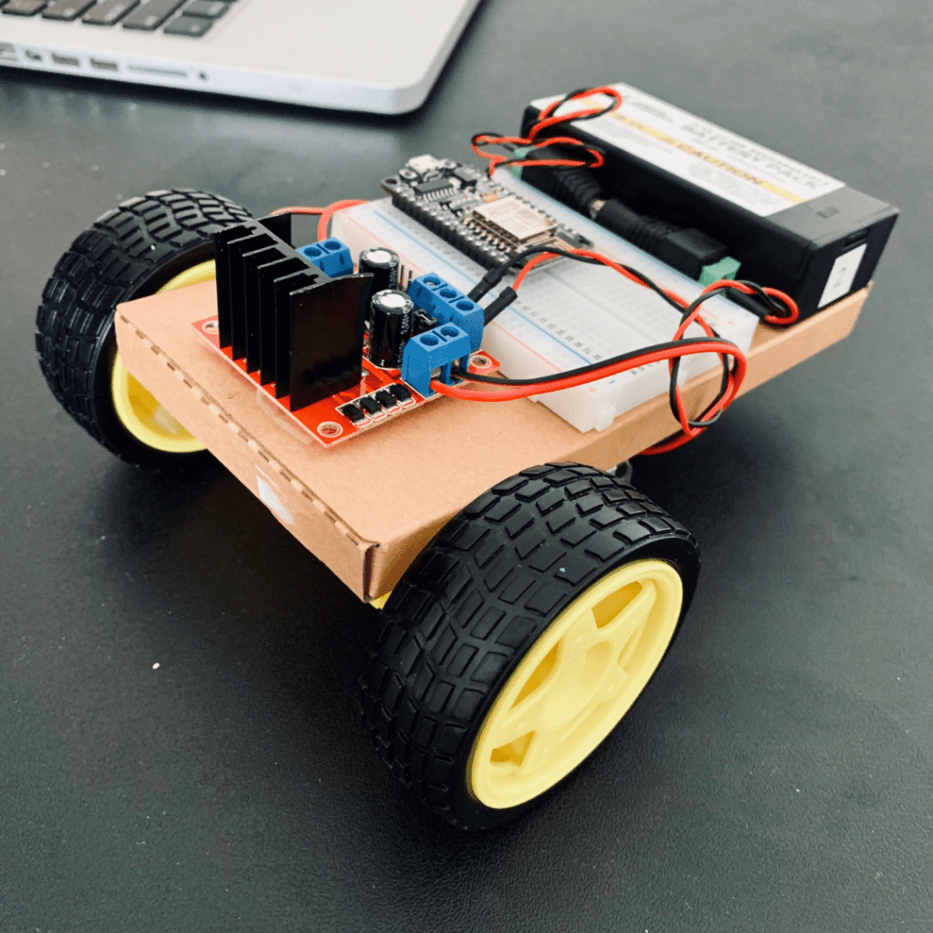
It’s easy to wire up a motor controller, but it can be challenging to power it for mobile applications. These examples show wiring diagrams for a pair of 3-6V DC motors powered by a 7.4V battery pack (2X 18650 batteries). Pick your controllers from the list, and use the wiring diagrams to complete your project. For convenience, you can also bookmark this page, and visit it the next time you’re building a mobile robot.
In this article, I’ve compiled the most popular or common configurations for connecting Motor Controllers L298N (Datasheet) and L293D (Datasheet) to the Raspberry Pi and Arduino (Uno, Nano, NodeMCU). I compiled this guide to keep all the resources and wiring diagrams in one place.
For easy navigation, you can click the links below to find the wiring diagram on this page.
Raspberry Pi Motor Controller Diagrams
As a reminder, the Raspberry Pi uses both Broadcom and Physical pin numbers for the GPIO pins. Broadcom pins are the GPIOXX reference and Physical Pins are the numbers corresponding to each pin’s physical location on the header. We will reference the Broadcom GPIOXX pins in the wiring diagrams below. So with that said, here’s a collection of popular Motor Controller Raspberry Pi wiring diagrams.

Click for Raspberry Pi Zero W pinouts
L298N Raspberry Pi Wiring Diagram
For this application, you’ll connect the L298N signal pins as follows:
L298N ENA to GPIO18
L298N IN1 to GPIO4
L298N IN2 to GPIO17
L298N IN3 to GPIO27
L298N IN4 to GPIO22
L298N ENB to GPIO12
You’ll power your Raspberry Pi using a 5V 2A battery pack.
L293D Raspberry Pi Wiring Diagram
The L293D is wired similarly. You’ll need to use a breadboard to wire up the L293D. Here are the signal pins between the controllers.
L293D Enable 1 to GPIO18
L293D IN1 to GPIO4
L293D IN2 to GPIO17
L293D IN3 to GPIO27
L293D IN4 to GPIO22
L293D Enable 2 to GPIO12
You can power your Raspberry Pi using a 5V 2A battery pack.
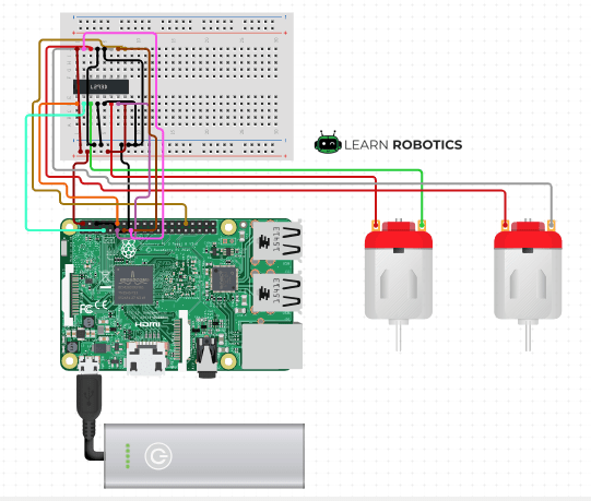
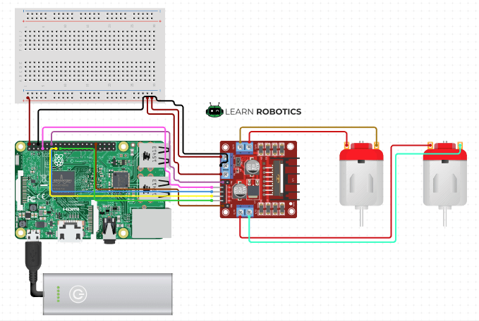
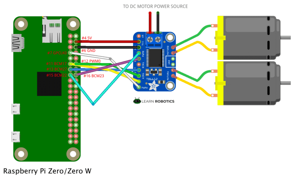
Adafruit TB6612 with Raspberry Pi
Lastly, you can use the TB6612 with the Raspberry Pi if you want to use an external DC Motor power source. Here’s how it’s wired:
TB6612 AIN1 to GPIO18
TB6612 PWMA to GPIO4
TB6612 AIN2 to GPIO17
TB6612 STBY to GPIO27
TB6612 PWMB to GPIO22
TB6612 BIN2 to GPIO23
If you’re not using Raspberry Pi, you can check out the Arduino Motor Controller diagrams for your project. I’ve compiled drawings for Arduino Uno, Nano, and NodeMCU.
Arduino Motor Controller Wiring Diagrams
If you’d rather use Arduino, you can check out this set of common Arduino Motor Controller wiring diagrams. To learn how to build a mobile robot using Arduino, check out this popular tutorial. You can also opt into our Robotics eCourse to learn more about mobile robots, programming, electronics, and compete in autonomous challenges. Enroll in the course here.
Arduino Uno L298N Wiring Diagram
The L298N is a pretty common controller used with the Arduino Uno. Connect the signal pins as follows:
L298N ENA to Digital 5
L298N IN1 to Digital 2
L298N IN2 to Digital 3
L298N IN3 to Digital 4
L298N IN4 to Digital 7
L298N ENB to Digital 6
Then you’ll power the L298N with a 7.4V battery pack. Be sure to share Ground between the Arduino, L298N, and battery pack. The 12V pin on the L298N plugs into the Vcc rail on the breadboard. Lastly, connect 5V from the Arduino to the Vcc rail on the breadboard and to the 5V pin on the L298N. You do not need to power the Arduino using the USB cable once your power pack is wired up.
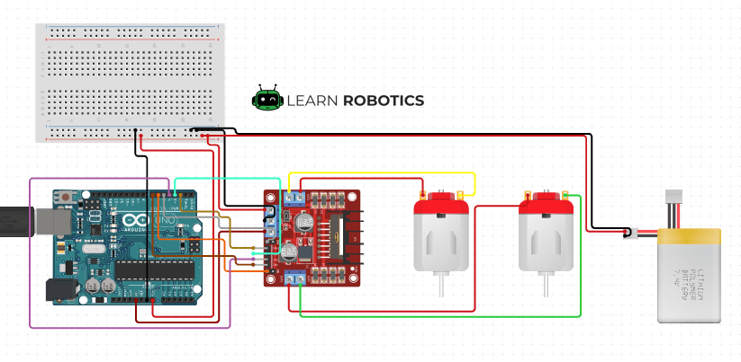
Ready to add autonomy to your robot? Learn how to program the L298N motor controller with Arduino in this tutorial.
Arduino Uno L293D Wiring Diagram
Here’s the L293D Wiring Diagram for Arduino Uno. The signal pins are connected as follows:
L293D Enable 1 to Digital 5
L293D IN1 to Digital 2
L293D IN2 to Digital 3
L293D IN3 to Digital 4
L293D IN4 to Digital 7
L293D Enable 2 to Digital 6
Then, attach the motor leads to the L293D, followed by the power between Arduino, motor controller, and battery pack.

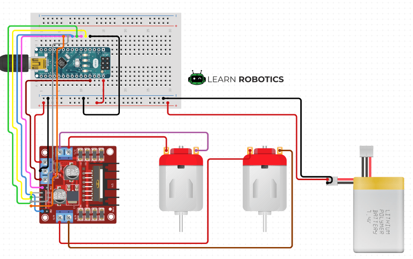
Arduino Nano L298N Wiring Diagram
Create a smaller Arduino Robot using the Arduino Nano and L298N motor controller. Connect the signal pins as follows:
L298N ENA to Digital 3
L298N IN1 to Digital 2
L298N IN2 to Digital 4
L298N IN3 to Digital 6
L298N IN4 to Digital 7
L298N ENB to Digital 5
Next, attach the motor leads to the side pins on the L298N. Then, wire up the power and ground leads to the breadboard. Be sure to connect power & ground for the nano, motor controller, and battery pack.
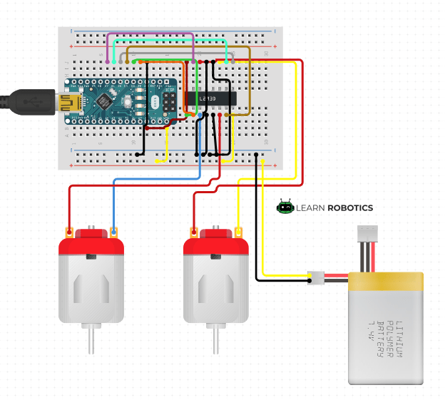
Arduino Nano L293D Wiring Diagram
Here’s how to wire the Arduino Nano to an L293D motor controller. Connect the signal pins as follows. Then, wire the power, ground, and motor leads together using the diagram, below.
L293D Enable 1 to 3
L293D IN1 to 2
L293D IN2 to 4
L293D IN3 to 6
L293D IN4 to 7
L293D Enable 2 to 5
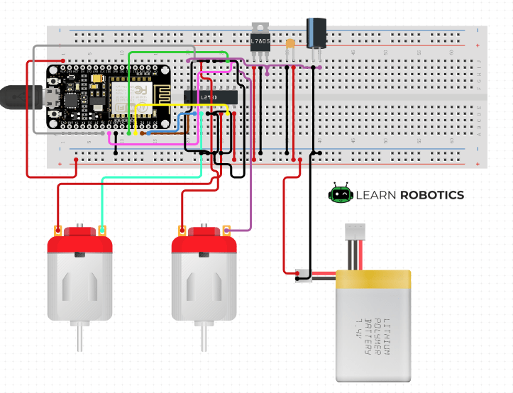
NodeMCU L298N Wiring Diagram
The NodeMCU requires an additional Voltage Regulator (L7805 – 5V 1.5A), an Electrolytic Capacitor (1uF/50V), and a Ceramic Capacitor (100nF – 0603). The signal pins between the NodeMCU and L298N are given as follows:
L298N ENA to D2
L298N IN1 to D1
L298N IN2 to D3
L298N IN3 to D4
L298N IN4 to D6
L298N ENB to D5

NodeMCU L293D Wiring Diagram
You can also use an L293D with your NodeMCU. Here’s how to connect the signal pins:
L293D Enable 1 to D2
L293D IN1 to D1
L293D IN2 to D3
L293D IN3 to D4
L293D IN4 to D6
L293D Enable 2 to D5
Lastly, you’ll want to verify your wiring and keep the controller powered off while downloading code. It’s good practice to add in a power switch off the battery pack to make wiring easier. The cool thing about these configurations, is once you have tried a few of them, you can make a mobile robot out of just about anything! Some projects include Tiny Robot Cars, Robotic Tanks, Robot Cars, and more.
Have you built any of these configurations?
I hope you find this article useful for your next mobile robot project! Tag us in your robotics projects on Facebook and Instagram!
Then, let me know what you think of this post in the comments section below. And, if you have a suggestion or correction for any of these wiring diagrams, be sure to include that in your comment as well.
Like these articles? Support the work we do by enrolling in an online course or signing up for a monthly membership. Our site is 100% powered on our growing community, so thank you for your continued support!


4 Responses
This post is really useful, this is the configuration I am using with my PiWars entry for this year, but I am using two L293Ds one for each motor because of the current requirements.
Glad you found it helpful, Philip!
Hallo,
I are a new builder fot this projrct.
My project is a crane.
I use 3 dc motors and one switch on/off.
I have 1 RPI 3b en 2 motormodules L298N.
Control smartphone android app with wifi .
Can you help me?
thanks,
Bert
Hey Bert, this is considered custom code, which we don’t provide solutions to in the comments section of our blog. You can book a studio lesson and we’ll be happy to help you 1-to-1 on your project. ~Liz from Learn Robotics