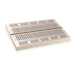
What is a Breadboard?
A breadboard is a plastic piece with conductive channels. It’s a solder-less way to connect wires, sensors, and devices to these ports to create prototypes, devices, and electronic circuits.
In this tutorial, we’ll show you how easy it is to get started with breadboarding!
Parts of a Breadboard
Breadboards are composed of three (3) parts:
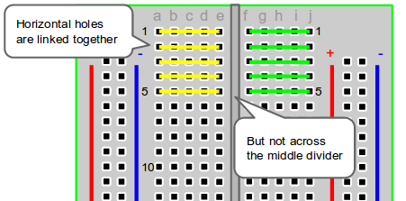
- Horizontal Rows (yellow and green lines)
- Vertical Columns
- Power (red) /Ground (blue) Rails
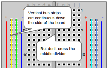
The middle divider separates both sides. So if wire power and ground to one side of the breadboard, you will also need to power/ground the other side.
When wiring a breadboard, be sure that the wires lay flat and are attached neatly to the board. It is good practice to label wires that are attached to important sensors or actuators, as well
Step 1 – Configure Your Power Source
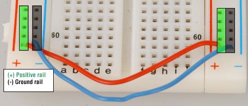
Next, let’s configure the power source. There are two sets of power rails that run along the edges of the breadboard. Rails are marked black/blue for ground (-) and red for power (+).
Each rail is independent of another, so you will have to connect the left positive rail to the right positive rail and the left negative rail to the right negative rail to supply power to both sides of the breadboard.
Here’s a visual of how to configure power to the breadboard:
Step 2 – Connect to Your Arduino
Once you’ve configured the power rails on the breadboard, you can use it to expand ports on a microcontroller, such as an Arduino.
How to power your breadboard using an Arduino
- Connect a red wire from the Arduino Uno 5V to the breadboard + power rail.
- Connect a black wire from the Arduino GND (ground) to the breadboard – ground rail.
Step 3 – Create a simple circuit
Finally, it’s time to practice wiring up a simple circuit. The only way to get good at making electronic devices is to practice!
Below are two examples for wiring up simple circuits using a breadboard. Give them a try, and as always, if you have questions, leave them in the comments section, below!
Example: Voltage Divider
We’ll go into details on the Voltage Divider in another article, but for now, understand that a Voltage Divider does exactly that: it takes an input voltage and reduces it to a smaller output voltage using a ratio of two resistors.
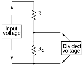
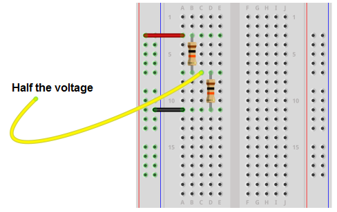
- Add the red wire from the power rail to the first resistor.
- Connect the Output of Resistor 1 and Input of Resistor 2 using the same row.
- Place the Yellow wire between Resistor 1_Out and Resistor2_In. This is half the voltage because both resistors are the same.
- Finally, the black wire is connected to Resistor2_Out.
Example: LED’s with Arduino
- Connect the positive + leg of the LED to the Digital signal on the Arduino and the negative – leg of the LED to a resistor that is connected to ground. The negative side of an LED is always the side with the flat edge.
- Attach a wire from the GND port on the Arduino to the ground terminal of the breadboard (black wire).
- Wire the 5V port on the Arduino to the signal column on the breadboard (bottom red wire). This provides power to the positive side of each LED.
- Power the system through the Arduino with the DC barrel plug (5-7.2V) or via the USB plug.
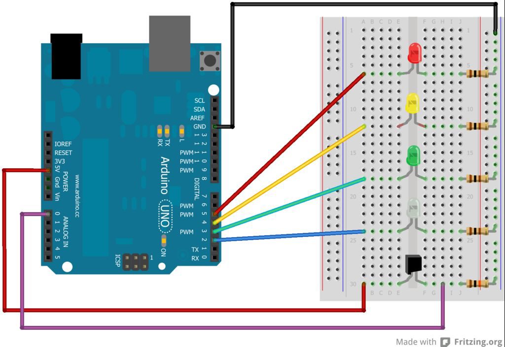
The red LED is connected to Digital port 5.
The yellow LED is connected to Digital port 4.
The green LED is connected to Digital port 3.
What port is the white LED connected to?
(answer: Digital port 2)
How to practice your prototyping skills
We have a few resources to help you practice and further your prototyping skills. I recommend our Level 1: Coding & Circuits course. You’ll learn how to program microcontrollers, wire circuits, read sensors, and create working devices—all from scratch!
Secondly, if you liked these projects, be sure to check out my 25 Arduino Projects workbook. This workbook includes a full-color wiring diagram and challenge prompts. For added difficulty, we’ve included “Extra Challenges,” questions, and prompts that can guide you through the answer. Get your copy, today!
[products ids=”8663, 49200″ columns=”2″ orderby=”id”]