 Ready to make your robot react to its environment using sensors?
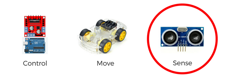
This week, we are focusing on Infrared Sensors to solve a common challenge in robotics: line following and avoiding.
Now is a good time to make sure your robot can move. If you haven’t completed lesson #3, I recommend checking that out first before proceeding with this week’s challenge.
Build a Mobile Robot to Line Follow: Objectives & Materials
Each week I will provide you with the objectives (goals of the lesson) and any materials you will need to complete the project.
I absolutely LOVE seeing what you guys are working on, so please don’t forget to tag me (@learnrobotics) on Instagram and Facebook with any progress you’ve made!
Part 4 – Goals & Objectives
- Learn about IR Sensors & how to wire them to the Arduino
- Configure IR Sensors in Arduino
- Setup IF Statements
- Complete Robot Challenges (Line Following & Avoidance)
- Time Duration: Approximately 4 hours. It’s another long lesson this week, so feel free to break it up into sections!
Materials for this Lesson
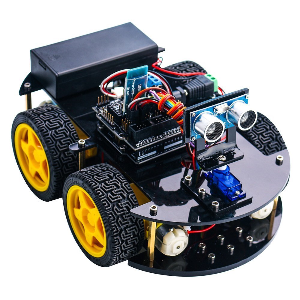
This tutorial series is based on the Elegoo Arduino Smart Robot Car kit. You can purchase the kit on Amazon for about $70. I recommend this kit because it provides a lot of value for the money and the components can be utilized in a number of robotic projects.
While you can follow along without purchasing the kit, it’s always more beneficial to be hands-on with a robot and try out the lessons for yourself. With that said, if you’re on a tight budget, I listed out the full components in Part 1 of this tutorial series.
Additional Materials
Required this week:
- BLUE Tape or BLACK Tape
- 2X IR Sensors (included in kit)
Included in Elegoo Robot Kit:
Other Materials:
- Multimeter
- Multitool (I use a Leatherman Wingman)
- Wire Cutters/Strippers
- Household Tool Set
- Screwdriver Set
- Drill (Faster to construct everything)
- Computer with at least 1 USB port (any OS is fine)
Time to start this week’s lesson!
What is an Infrared (IR) Sensor?
Before we jump into the science behind IR sensors, I want to give you a couple visuals in case you’ve never seen an IR sensor before.
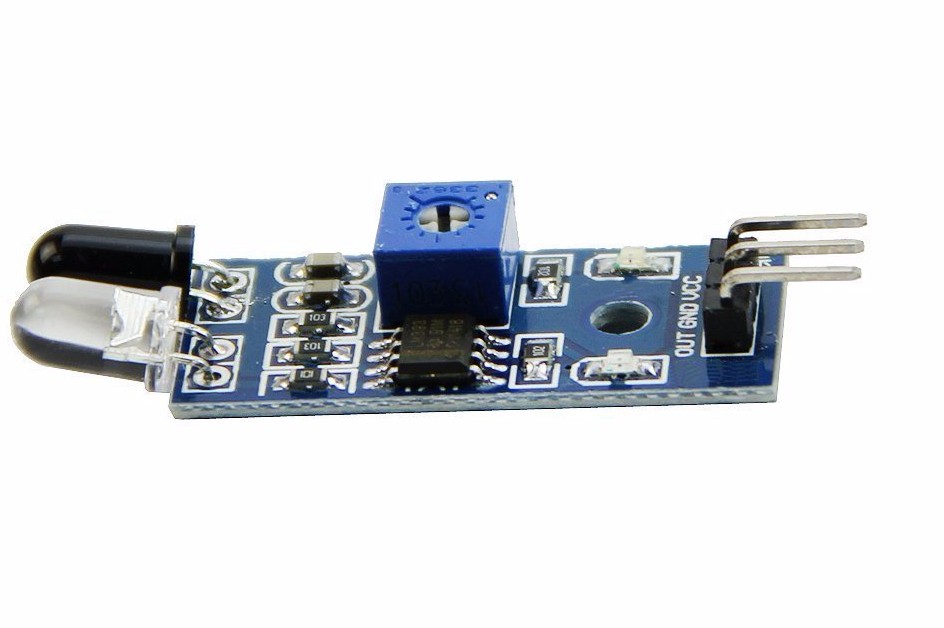
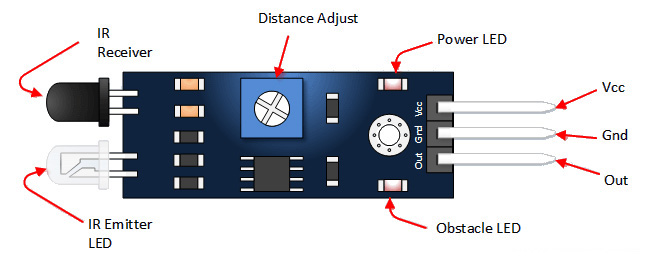
As you can see, an IR sensor is composed of two LED’s, a potentiometer, and has 3 pins (GND, VCC, OUT, in no particular order). There’s also an LM393 comparator chip built-in that takes the reading and sends it through the signal (OUT) pin for input to the Arduino.
If you haven’t already done so, go ahead and grab your IR sensors from your kit. Take a look at them, and see if you can identify all of the components on the sensor.
You’ll notice that the IR sensors above are slightly different. The one on the right (like our kit) is specifically designed for line detection, whereas the one on the left is designed for object detection & distance measurements. You can use either for this activity. If you’re using the IR module that looks like the first picture, I recommend wrapping the LED’s with some electrical tape to help with interference.
IR Sensors run on an input voltage (VCC) of +5V. You’ll want to provide power and ground from the Arduino. We’ll talk more about wiring soon, but while we have this diagram up, I wanted to mention this in case you were wondering.
How do IR Sensors work?
Unlock this content by entering your email below! It’s completely FREE!
[pretty-locker id=”339508″]IR sensors work by emitting a beam of infrared (IR) light and measuring the reflected signal.
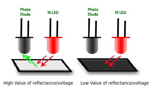
Based on the diagram above, how do you think we can use this information to make our robot follow a line?
When our robot is positioned on the floor, we can use a high-contrast color tape (like blue or black for light-colored floors, or white or tan for dark color floors) and use the reflectance value to determine whether or not to move forward or away from that color.
This concept provides us the foundation for line following. Line avoidance can be achieved by reversing our logic. Instead of moving toward the tape, we want to stop, back up, and turn around when we detect the tape.
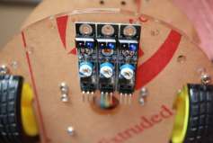
Based on the photo above, we can make an educated guess that the (light) floor will have high values and the blue floor will have low values. One thing to consider, is that if your potentiometer is rotated, you may have opposite results compared to our prediction. The way to fix this is to play around with the knob until you have readings that differ enough to make decisions off of.
So that’s about as much information you need to know about IR sensors and communication for this lesson, but if you’re more curious about this topic, I recommend checking out this article by Sparkfun. Read on to find out how to wire up the IR sensors to your robot.
How to wire an IR Sensor to our Robot Car Using Arduino
Remember how we talked about data sheets in the previous lesson?
Well, here’s the data sheet for the IR Sensor (see page 8, KY-033) I’m using with the Elegoo Smart Robot Car kit.
Otherwise, you can use this Fritzing model to connect your IR sensor.
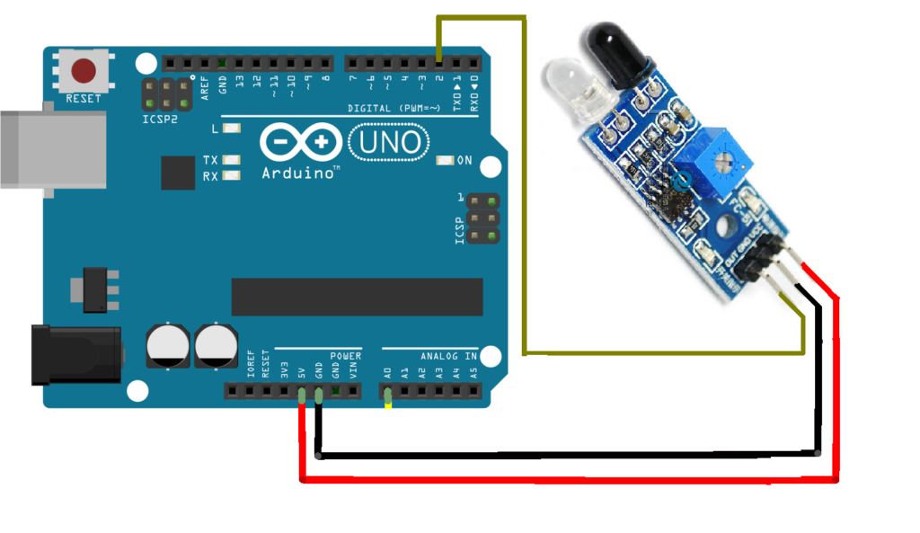
You’ll notice that we have the signal line connected as a Digital input on pin 2. While some of you might disagree with this configuration, hear me out.
The goal of this project is to have our robot follow or avoid lines.
Therefore, we only have two conditions that we need to know: 1) On the Line and 2) Off the line/on the floor
Because digital inputs provide us an on/off, true/false, 1/0 signal, this might be enough to differentiate between being on the floor vs being on the tape. And bingo! By all means we can use this to solve the problem.
Now, let’s wire up our IR sensors. Note: Your wire colors DO NOT need to match the wire colors in the diagram!
Red: +5V
Black: GND
Yellow: Signal – Connect to Digital Pin 2.
Add a second IR Sensor by connecting the Red & Black to +5V and GND, respectively, and the Yellow Signal to any open Digital Pin (I’ll pick pin 12).
You can configure a third IR Sensor in the same way as the second and first. Just utilize any open digital pin for the signal wire.
Should we use an Analog pin for our IR Sensor?
In some circumstances (interference particularly), a boolean signal is not enough to truly differentiate which state we are in. So if you find yourself testing the digital configuration and you’re getting true readings all the time regardless of the tape begin there, you can… A) try calibrating the sensitivity of the IR sensor using the potentiometer dial, or B) switch the signal pin to an Analog input (pin A1).
Then, when you receive your reading from the IR sensor, you’ll get a range of values from 0-1023. From this we can designate our threshold for driving on the tape and a range of values for when we’re on the floor.
If you’re wondering why 0-1023 is the “magic” range, it’s because the Arduino has a 10-bit analog-to-digital converter. So that signal is effectively 210 = 1024, and the range is 0-1023. You can read more about analog signals in the Arduino documentation, here.
The field of robotics is a lot of trial and error. I recommend configuring your robot both ways and learning which methodology works best for you during this exercise.
IR Sensor Software Setup for Robot Car Using Arduino

For the purpose of this tutorial, I am going to continue on using the digital configuration.
We’re going to use two IR sensors for this example. The left IR is on pin 2; the right IR is on pin 12. The goal is to connect our IR sensors and then read the data from both sensors every 5 seconds. We’ll display the data using print lines to the serial monitor.
How do we configure our left and right IR sensors in a sketch?
Before I tell you the answer, go ahead and open up my article, Four Steps to Writing An Arduino Program.
Using that methodology, create an outline of what we want to do.
- 1) Define Your Program
- 2) Declare Each Input/Output (I/O)
- 3) Create Appropriate Method(s)
- 4) Call Your Methods in
loop()
Don’t cheat yourself either. I see you there!
I purposely didn’t paste the code here, because I knew you’d be tempted to just copy it, without giving it a try yourself! 😉
IR Sensor + Arduino Code Walk-Through
This premium section is part of our Robotics eCourse. I recommend joining it if you’re looking to build your robotics, electronics, and programming skills. All from the comfort of your home!
On top of in-depth review of solutions, code samples, and interaction with our instructors, you’ll also gain access to our quizzes, projects, and a Course Certificate.
Click here to enroll in the Robotics eCourse!
See you in the course! 🙂
Let’s Talk about Conditions & Responses
We’ll be using IF statements to check to see if a specified condition is met. IF statements only run the code when the given condition is satisfied. Oftentimes they’re used when determining how to respond based on the current state.
If the specified condition happens, do this, else do that.
Here’s what that looks like in our Arduino sketch.
if(condition){
   // do this
else{
  // do that
}
There are more sophisticated IF statements that you can use, but for the purposes of this activity, you shouldn’t need to get much more complicated than checking for a single condition.
But, in case you’re curious, you can put an IF statement in the body of an IF statement to check a condition once a condition has been met. This is called nested IF Statements, which we will learn more about in a future lesson.
But for now, let’s talk about writing the condition statement.
When comparing values, you will use BOOLEAN OPERATORS:
- && and
- || or
- ! not
- == checking for equality
- = setting a variable equal to
- > greater than
- >= greater than or equal to
- < less than
- <= less than or equal to
Instead of explaining each one, I will show you an example for each.
Ex. 1 To check if valueA=1 and valueB=7, you will write it like this:
if(valueA=1 && valueB=7){
    // ...code here...
}
Ex. 2 To check if valueA=3 or valueB=9 you will write it like this:
if(valueA=3 || valueB=9){
    // ...code here...
}
Ex. 3 To check if valueA is not equal to 10, you will write it like this:
if(valueA != 10){
   // ...code here...
}
Ex. 4 To check if valueA is equal to valueB, you will write it like this:
if(valueA == valueB){
    // ...code here...
}
The code will run only if valueA and valueB are the same value.
Ex. 5 To set valueA is equal to valueB you will write it like this:
valueA = valueB
Ex. 6 To check if valueA is less than valueB you will write it like this:
 if(valueA < valueB){
    // ...code here...
}
You can use less than or equal to, greater than, and greater than or equal to in the same way. Less than or equal to and greater than or equal to includes the number you’re checking in the condition.
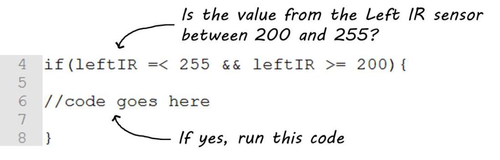
i.e. valueA <= 10 means that if valueA is less than 10 or equal to 10, the condition will be met, and the IF statement will be executed.
Here’s an example of an IF Statement with a Condition Statement.
Create an IR Sensor Method
Now, we are ready to create a method to check our IR Sensors.
One method we will write is bool onTape(int IRsensor). Here’s the method information.
Return Type: boolean (bool)
Method Name: onTape
Input Parameters: int IRsensor
Function: Checks if a specified IR sensor is on the tape. If it is, it returns TRUE.
bool onTape(int IRsensor){
// code here ...
   return true;
}
Try to use the information above to create your onTape(int IRsensor) method before continuing on.
Another method we will write is bool onTape(int IRsensor). Here’s the method information.
Return Type: void (void)
Method Name: lineFollow
Input Parameters: both IR sensors and their respective thresholds
Function: Line follow program – the robot will follow blue lines taped on the floor.
void lineFollow(int irLeft, int irRight, int thresholdL, int thresholdR){
// code here ...
}
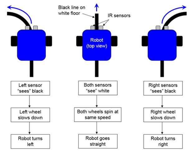
How the program should look, logically…
Once we know whether or not we’re on the tape, we can maneuver the robot left or right to either FOLLOW or AVOID the lines. A flowchart visual of this logic is shown below.
Translate these steps into Arduino code
- Check: IF STATEMENT – is the leftIR on tape?
Yes – we want to move left (to stay on the tape) - Check: IF STATEMENT – is the rightIR on tape?
Yes – we want to move right (to stay on the tape) - Continue moving in the current direction until one sensor reads “floor”
We will use our onTape(), move()and IF STATEMENTS to develop the code.
Tying it all together
Create the lineFollow() method described above. When you’re finished, add this method to your loop() and test it out!
TIP: Write a little bit of code, compile, and run it on the robot. Make adjustments as you go. It’s very difficult to troubleshoot code when you’ve written a lot of it!
Once you have it working, you’re ready to tackle the next sensor project: obstacle avoidance! We’ll cover the fundamentals of detecting objects in the next lesson. Head on over to part 5 to add this feature to your robot!
If you liked this article, you’ll LOVE our eCourse.
Join our Robotics eCourse and go beyond these tutorials with interactive lessons, discussions, projects, and a course certificate! Click here to enroll.