Hello LR Nation! I’m back with Week 3 of the Beginner Bots Tutorial Series. Who’s loving this Robotics tutorial series? If that’s you, go ahead share it (link to Facebook) with your friends!
We also have a full Robotics eCourse that dives more into analysis, interactive projects, and includes a completion certificate! Check that out here, if you need a little more accountability with learning this content!
This week, we are focusing on drivetrains, data sheets, and writing code to enable our robot to move. If you haven’t read Part 1 or Part 2 of this series, I recommend checking those articles out first before starting this lesson! Now, let’s dive into the lesson for week 3!
Build a Mobile Robot Lesson #3 – Objectives & Materials
Each week I will provide you with the objectives (goals of the lesson) and any materials you will need to complete the project.
I absolutely LOVE seeing what you guys are working on, so please don’t forget to tag me (@learnrobotics) on Instagram and Facebook with any progress you’ve made!
Part 2 – Goals & Objectives
- Understand the drivetrain & turns
- Learn how to read a data sheet
- Program the robot to Move (Forward, Backward, Left, Right)
- Complete the first Robot Challenge
- Time Duration: Approximately 6 hours. This is a longer lesson, so feel free to break it up into sections throughout the week!
Part 2 – Materials for this Lesson
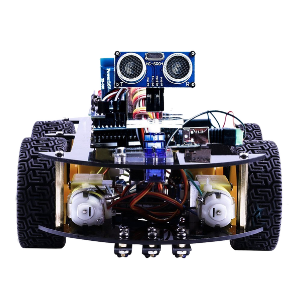 This tutorial series is based on the Elegoo Arduino Smart Robot Car kit. You can purchase the kit on Amazon for about $70. I recommend this kit because it provides a lot of value for the money and the components can be utilized in a number of robotic projects.
While you can read these articles without purchasing the kit, it’s always more beneficial to be hands-on with a robot and try out the lessons for yourself. With that said, if you’re on a tight budget, I listed out the full components in Part 1 of this tutorial series.
Additional Materials
- Included in Elegoo Robot Kit:
- L298N
- Arduino Uno
- Arduino Uno Sensor Shield V5
Other Materials:
- Multimeter
- Multitool (I use a Leatherman Wingman)
- Wire Cutters/Strippers
- Household Tool Set
- Screwdriver Set
- Drill (Faster to construct everything)
- Computer with at least 1 USB port (any OS is fine)
Let’s ease into today’s lesson with a quick talk on drivetrains and turning.
Drivetrain & Turning a Mobile Robot
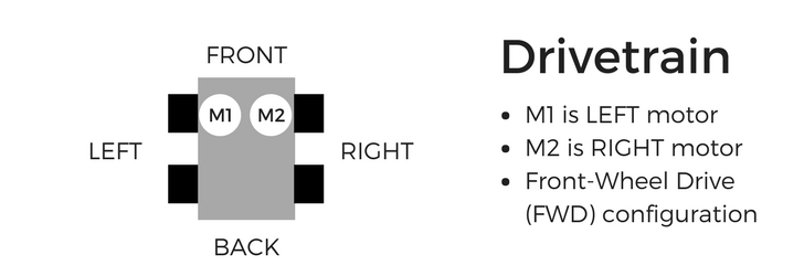
First, let’s talk about a robot’s drivetrain. This model is 2WD, but the same principles apply for 4WD systems.
When we move, we want to be able to go forward, backward, left, and right.
Let’s talk first about moving forward and backward.
When we want to move our robot forward, the left motor spins counter-clockwise (CCW) & the right motor spins clockwise (CW). Backward will be opposite: the left motor spins CW & the right motor spins CCW.
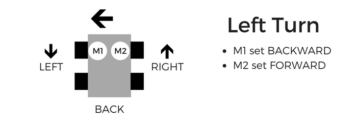
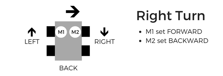
When we turn, we want to set the motors on either side to run in the opposite direction. Therefore, when we want to make a left turn, we set the left motor backward & right motor forward. For a right turn, we set the left motor forward & right motor backward. I created the diagrams above, to help you visualize how this works.
Using Data Sheets
We will use a datasheet to provide movement to the robot.
A data sheet provides you the electrical wiring and configuration information about a circuit board. They’re created by manufacturers (more specifically the Electrical Engineer who designed the electronic circuit board) and are similar to cooking recipes. If you want to build your own board or understand how the circuit works, you’ll refer to the board’s data sheet.
Sign-in to unlock the rest of this content. It’s completely FREE, just enter your email below.
[pretty-locker id=”339508″]The most important thing you need from the data sheet is the pin configuration.
The pin configuration tells you how each port functions and where they are located. You can find any data sheet online by typing in the name of the board followed by the words “data sheet Arduino” into Google.
You’re in luck! Here’s a link to the L298N data sheet.
L298N Pin Configuration
We are using the L298N to control our motors. The L298N is an H-Bridge circuit that can drive a current in either polarity and be controlled by Pulse Width Modulation (PWM). If you have the V3.0 kit, your L298N has built-in JST connectors. Click here to jump down to that section.
The pins are configured as follows:
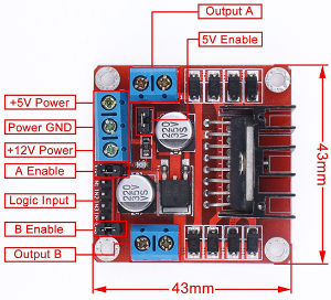
To use the L298N motor controller with the Arduino, you will need to understand its inputs and outputs.
- Output A: Motor A lead out
- Output B: Motor A lead out
- +12V Power: Source from 5V-35V, just marked as 12V
- GND: Ground
- 5V: 5V input (unnecessary if your power source is 7V-35V, if the power source is 7V-35V then it can act as a 5V out)
- EnA: Enables PWM signal for Motor A
- Logic Input:
- In1: Enable Motor A
- In2: Enable Motor A
- In3: Enable Motor B
- In4: Enable Motor B
- EnB: Enables PWM signal for Motor B
V3.0 L298N Motor Controller
The V3.0 Robot Car includes modules with JST connectors. This motor controller works the same as the traditional version. The only difference is you’ll wire each module using a connector cable instead of individual jumper wires. This actually makes the wiring a lot easier. Refer to the diagram below.
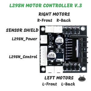
The L298N motor controller works by using principles of Digital Logic gates. We’ll be setting the motor inputs to either HIGH or LOW to change functionality of the pin. We will not get into detail about Digital Logic circuits in this course, but if you’d like more information, here’s a great resource.
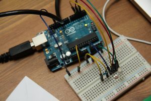
Program Arduino Robot to Move using L298N Motor Controller
In the previous lesson, we wired up the Arduino Sensor Shield and Motor Controller using the picture above for reference. Now, let’s take a look at how we define each pin to configure the motors in the software.
Understanding Variables
It’s beneficial to give pin locations a name that’s easy to remember what we connected to it. Therefore, we will define these names in our program as variables.
There are two types of variables in a program: 1) global and 2) local.
What is a global variable?
A global variable is the name of an element you can use anywhere in the sketch.
They’re defined at the top of the code before the method definitions and after the program comments. You will use the datasheet to determine what you want to name the global variables to make it easier for reference.
What is a local variable?
A local variable is the name of an element you can use within the body of a method. It is local to the function it is defined in. Therefore, you cannot use a local variable anywhere in the sketch.
Global = whole program
Local = only within the method it’s defined
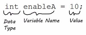
To define a variable, use the data type (String, int, char, etc.) followed by the variable’s name = value and then a semi-colon.
Here’s the coding syntax:
The most common Data Types we will use for this course are Boolean, Integer, and Void.
Boolean (bool) –true/false, 1/0, yes/no
Integer (int) – a whole number
Void (void) – returns nothing
For our pin configurations, we will use global variables. See the example code, below.
/** Global Variables **/
//Left Motor
 int enableA = 10; //enable connected to pin #10
 int motorA1 = 9;
 int motorA2 = 8;
//Right Motor
 int enableB = 5;
 int motorB3 = 7;
 int motorB4 = 6;
Don’t forget the semi-colon at the end of each declaration, or your code will not compile!
Now that the code is set up and the board is wired, verify that these statements are true:
- Enable A is connected to pin 10 on the Arduino.
- Input 1 is connected to pin 9 on the Arduino.
- Input 2 is connected to pin 8 on the Arduino.
- Enable B is connected to pin 5 on the Arduino.
- Input 3 is connected to pin 7 on the Arduino.
- Input 4 is connected to pin 6 on the Arduino.
Your wiring should match your code & your code should match your wiring.
Next, configure setup() method using the datasheet. Once you’ve defined your global variables (the motor pins), we’ll use the datasheet to configure the pins as inputs/outputs or high/low.
pinMode() and digitalWrite() are built-in methods defined in the Arduino Library. We’re “calling” these methods when configuring the setup. We’ll learn more about “calling a method” in next week’s lesson. For now, let’s develop our own methods
How to Create a Method
There are 3 Parts to Defining a Method:
1. Return Type: Are you calculating something that has an answer? Do you want to use this answer later? If so, what’s the data type of that answer? (String, int, char, etc.) If not, use the type, “void.”
2. Method Name: Give your method a name that makes sense. (i.e. if your goal is to “move”, then name the method “move()“).
3. Input Parameter(s): This is optional. If you want the method to “take in” values for use in commands or calculations, you can define them within the parentheses. Be sure to include the data type (String, int, char, etc.) before the parameter name. If you don’t have any input parameters, use a set of empty parentheses (i.e. move()).
Once you’ve defined your method, you can develop commands and calculations for the method within the method body. Sometimes you’ll want to “return a value” from your method. In the example above, we are calculating a sum of two numbers. We will want to retrieve the answer to the calculation, so we include a Return Statement in our method.
In mathematical terms, we are completing this calculation:
a + b = sum
We will return the answer as an integer, which is why the return type is defined as int.
You can apply this technique anytime you want to obtain a value from your method. This isn’t limited to integers either; you can also return Strings, char, float, etc.
Robot Practice Problems – Defining Methods
What does the method subtract() look like?
Leave your answer in the comments section, below! Feel free to post a link to a public gist or your Github account.
The move() method
Now that you know what a method is, and how to construct one, let’s create the move() method for our robot.
As we develop new methods, it’s good to get in the practice of defining the 3 Parts from above before typing out the solution.
Return Type: void
Method Name: move
Input Parameters: int motorPin1, int motorPin2, int speed, int duration
Functionality: Move a motor for a set duration
Translate that to code, and it should look like this (Step #1):
Now let’s give this method some functionality (Step #2).
Here’s a step-by-step list of things we want to do.
- Turn on the motor
- Set the speed
- Run for a specified time
We will use the digitalWrite(),analogWrite(), and delay() methods to develop the code.
Read through the code and see if you can find one tiny flaw…Did you find it? Yep…this method only controls ONE motor…
How do we use it to control both motors?
This code only controls ONE motor. We can use the method for both motors using two separate method calls. It’s your turn. Now that we can move, we also need to be able to STOP.

Robot Practice Problems – Programming Moves
Give these practice problems a try before completing this week’s robot challenges! The problems build on one another, so I recommend attempting them in order.
#1 – Create the stop() method.
Hint: What are the input parameters? What is the return type? Use the 3 required parts to create your answer. Also, the move() method is the opposite of what you’re trying to do with stop. How can you modify move() to create your solution?
Once you’ve completed the practice, here’s how we’d use both move() and stop() in the loop() method.
#2 – Create Movement Methods
Using the descriptions at the beginning of the article for turns, create the following methods:
- forward()
- backward()
- left()
- right()
You can re-use the move() to create the above movements. It’s better to re-purpose code than to re-write the same lines.
If you’ve taken a class with me, I refer to this as the “universal move() method.” What that means is that I have one method that allows me to do EVERY move. Hence why it’s called the universal move() method.
Write and test these methods, then you’ll be ready for Part 4! A big part of robotics is using sensors to respond to the environment. In Part 4, I’ll show you how to solve a common problem in robotics: line following. If you’re ready, click here to begin the next lesson!
Looking for More Robot Challenges?
Join our Robotics eCourse and go beyond these tutorials with interactive lessons, discussions, projects, and a course certificate! Click here to enroll.