

In this article, I will show you a quick and easy way to attach a light sensor to your robot to follow or avoid light.
But first, how will we detect light?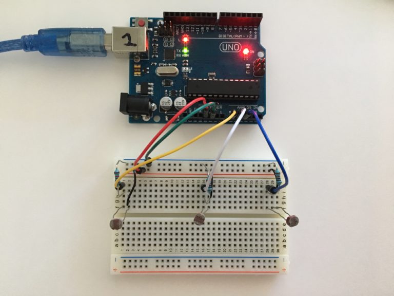
We will be using photoresistors to determine brightness. A photoresistor, or photo cell, is a light detecting resistor (LDR). Photoresistors act just like regular resistors, but they change in response to the amount of light detected.
Create the Circuit using a Wiring Diagram
The easiest way to use the photoresistor is to connect it to another fixed value resistor in a voltage-divider arrangement. The Voltage Output will drive the Analog Input signal on the Arduino.
We can then compare values printed to the serial monitor to determine if it’s bright or dark.
In this configuration, high values yield a brighter signal, and low values yield a darker signal.

If that’s a little confusing for you to understand, no worries, I’ve outlined each step of the project below. For those of you who are more advanced, and familiar with Arduino, resistors, and I/O, then feel free to wire up your circuit and to skip to Step #2 – Write the Software.
This tutorial assumes you have a fundamental understanding of Arduino programming, Breadboarding, and have built an Arduino or GPIO-compatible mobile robot. You’ll also need to have the code written to command your robot to move. If not, please check out my articles on Simple Arduino Programming and Breadboard wiring before starting this tutorial.
Now, let’s grab the list of materials, and get started!
Materials to build the Light Sensor Array
- Arduino Mobile Robot (I used this one)
- 3X Photoresistors
- 3X 10K Ohm resistors
- Breadboard
- Jumper Cables
Step 1 – Create the Light Sensor Array on a Breadboard
Follow the diagram below to connect the resistors, LDR’s, and jumper cables to your Arduino or Arduino Sensor Shield on your robot.

Step 2 – Write the Software to Obtain Photoresistor Readings
I like to create a prototype of the sensor board using just an Arduino and the sensor, write the code, and test it out before mounting it to my robot. If you don’t have an extra Arduino to test with, feel free to mount the breadboard to your robot and then proceed with this step.
Print Readings to the Serial Monitor
The first test we need to do is figure out our threshold for brightness. If we shine a flashlight on our sensor, which values correlate to this brightness?
To determine the answer to this question, we’ll print the readings from each photoresistor to the serial monitor in the Arduino IDE.
Here are the high-level process steps for this section:
- Open up the Arduino IDE. Create a new sketch.
- Configure your three photoresistors as INPUTS.
- Begin the serial monitor.
- Print the readings every second to the serial monitor.
I recommend trying to set up the code yourself, before downloading the code. You’ll learn a lot more if you try to figure it out yourself.
Step 3 – Move the Robot towards “Brightness”
Now that we have the threshold figured out for our photoresistors (reading > 950), we can write the code that triggers the robot to move.
I’ve written an Arduino Robot library called “Create” for the robots using the L298N controller, which I will be using in this tutorial. If you’ve already written the motor controller functions for your robot, you don’t need to use this library, just command your move() or forward() method when the brightness reading is above 950.
If you haven’t written the code to make your robot move, I recommend configuring that first before proceeding with this tutorial. If you’re stuck, you can clone and use my Create library so long as your robot uses the L298N motor controller. Be sure to read the “README.md” on Github to ensure you have the motor signal wires plugged into the correct pins.
Determine which sensor has the highest reading
Since we have 3 sensors, we need to check all of the readings and determine which one has the highest value. The highest value tells us which side of the robot is the brightest.
To do that, we’ll create a method called, getHighest(). We’ll use the following steps:
- Get readings from all three sensors
- Compare readings using an if statement
- Return the sensor that has the highest reading
int getHighest(){
   //get sensor readings from our 3 photoresistors
   int left = analogRead(ldr1);
   int center = analogRead(ldr2);
   int right = analogRead(ldr3);
   if(left > center && left > right){
      return 1; //1 will signify the left sensor is highest
   else if(center > right){
      return 2; //2 will signify the center sensor is highest
   else{
     return 3; //if left or center isn't highest, then right probably is.
   }
}
Develop a method that contains the logic to move
Now that we know which side is highest, we will use conditional logic again to move our robot toward the light, accordingly.
To do that, we’ll create a method called, moveToLight(). We’ll use the following steps:
- Get the highest reading
- Compare situations using a Switch Case statement
- Move the robot in the appropriate direction by commanding the motors
int moveToLight(){
  int highest = getHighest();
  int mSpeed = 150;
  switch(highest){
    case 1: //light is on the left
      robot.go(-mSpeed,mSpeed+20,0); //move left
      break;
    case 2: //light is center
      robot.go(mSpeed,mSpeed,0); //move foward
      break;
    case 3: //light is on the right
      robot.go(mSpeed,-mSpeed-20,0); //move right
      break;
    default: //no light detected move foward
      robot.go(mSpeed,mSpeed,0); //move ahead
      break;
  }
}
Remember, I’m using the Create library to command my robot to go. So this line of code, will not work on your robot unless you’ve installed the Create library and configured the settings as outlined in the Create README.md.
robot.go(mSpeed,mSpeed,0);
If you have your own commands for moving your robot, replace the “robot.go…” lines with your methods. Be sure to use the correct directions!
Lastly, we’ll call our moveToLight() method in the loop() method to execute the code on the robot.
void loop(){
   moveToLight();
}
Step 4 – Try it out & Make Adjustments!
Welcome to the fun part of this tutorial! We’re going to have our robot follow us around!
Download the code onto the robot, bring out your flashlight, and see how it works!
Does the robot move towards the light as expected? Do you need to adjust the brightness threshold? Run some tests like these to tune your robot and improve the responsiveness. Remember, you won’t necessarily have it working perfectly on the first try. And that’s OKAY! Part of robotics is starting off with a foundation and making improvements.
Final Thoughts
While this light following Arduino robot wasn’t too difficult to make, there are some additions I would consider adding to make it better.
- Rotate the Servo in the direction of the brightness
- Calculate a weighted average of brightness to make better judgement before moving
- Tune the motors to ensure smooth movement
- Create a case or mount for the photoresistors to secure them in place while the robot is moving
Did you try this tutorial?
If so, don’t forget to leave a comment below with your thoughts and solutions! I’m a huge fan of video, so if you’ve made a robot using this sensor, post a link to your YouTube video showing it off!
As always, if you have questions, you can drop them below or DM me on Instagram @learnrobotics.


2 Responses
hello Liz, I am trying to make a light following robot using a Darlington pair. could you assist?
Rahim, Check out this post on creating a circuit to read brightness. You can use a second transistor to create your Darlington pair.