The Raspberry Pi is a single board computer that also has a set of GPIO pins. GPIO stands for General Purpose Inputs and Outputs. Like Arduino, you can use the GPIO pins to attach sensors and electronic components. This tutorial is designed to give you a crash course in Raspberry Pi GPIO pins, and how to use them in code.
The first step in using any GPIO pins is to gather the pinout from the data sheet. For this tutorial, we will refer to the Raspberry Pi 3 B+ model. You can use the steps in this tutorial for other flavors of Raspberry Pi so long as you use the pinout for that board. This tutorial also assumes you’ve already configured your Raspberry Pi and are ready to interface the GPIO pins with sensors.

Here’s a link to the Raspberry Pi 3 B+ pinout (full size). There’s also an interactive website on Raspberry Pi GPIO. It’s a pretty cool tool if you’re looking to learn more about the features of each pin.
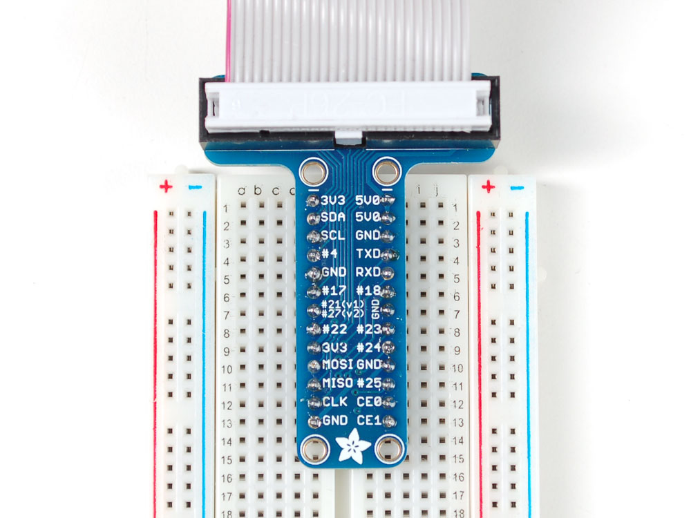
If you plan on wiring up components to a breadboard, then you may want to use a GPIO breakout board and connector cable. This makes it easier to wire up breadboard components to the pi.
GPIO Naming Convention
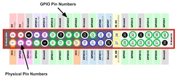
To make things interesting, the Raspberry Pi has two sets of pin numbers. One set is the GPIO or Broadcom (BCM) number, which is what you’ll reference in code (RPi.GPIO and GPIO.Zero). In the pinout diagram, the GPIO pin number is located around outside the red rectangular box.
The other set of pin numbers is the Physical pin number that identifies the location on the circuit board. In the pinout diagram, the Physical pin number is located inside the red rectangular box inside the circle.
Here’s a diagram for your reference. Don’t mix these two naming conventions up, because more often than not, they’re not the same pin!
Each Pin has a Functionality
Now that we know how the pins are named, we can use the GPIO labels to learn more about the functionality of the pin. You’ll notice that some pins don’t have a GPIO prefix. That’s because they do not serve as a General Input or Output. Some examples of this are Physical Pins 1, 2, and 4. Those are reserved for 3V and 5V power, respectively.
There are also a number of Ground Pins (Physical Pins 6, 9, 14, etc.). Furthermore, there are GPIO pins that have dual functionality. A prime example of this are the GPIO/UART combo pins (Physical Pins 9 & 10) and GPIO/SPI, GPIO/PWM pins. Lastly, there are some ID_SC pins (Physical Pins 27 and 28) that are used for i2c communication with an EEPROM (Electrically Erasable Programmable Read-Only Memory).
GPIO Limitations: Where are the Analog Pins?
As you begin designing systems that use the Raspberry Pi GPIO, it’s important to understand what functionality you’ll need as well as the limitations of the Raspberry Pi architecture.
One big limitation is that there isn’t an on-board Analog-to-Digital Converter (ADC). This means, you cannot use Analog Sensors with the GPIO pins directly. You’ll need to wire up an external ADC, such as the MCP3008 ADC, and use that to feed data to the pi.
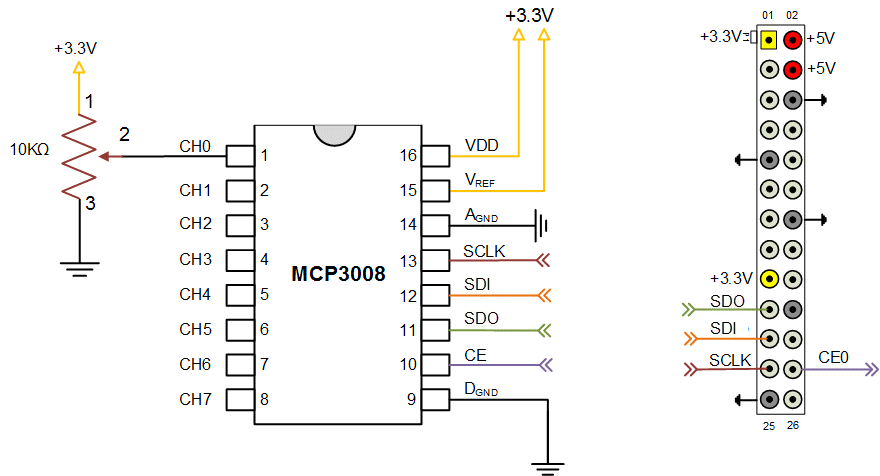
Above is a wiring diagram in case you’d like to gather 10-bit readings (210 = 1024 in the range of 0-1023) from a photoresistor, light sensor, or other analog sensor. Notice that the top-left pin on the right pinout diagram represents the Raspberry Pi Physical Pin 1.
I also want to point out that if you’re using digital sensors, you can feed the signal into any of the GPIO pins and you’ll be all set. This configuration is just for analog signals requiring more than a single bit of data.
Raspberry Pi GPIO Python Libraries
Now that you know how to read the Raspberry Pi GPIO pinout, and the functionalities of the pins, it’s time to learn how to write some code collecting and outputting data. First, let’s talk about some popular Raspberry Pi GPIO Python libraries: GPIO Zero library and the RPi.GPIO library.
GPIO Zero is a wrapper to the RPi.GPIO library. This makes it very easy to use (for beginners) and provides a lot of functionality right out of the box. RPi.GPIO allows you to work directly with sensor signals and build up your own functionality. Here’s a good explanation of the differences between GPIO Zero and RPi.GPIO.
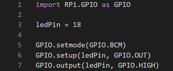
Rather than importing a module (like an LED), the RPi.GPIO library allows you to import a GPIO and then build functionality on top of it. This makes it useful if you want to debug data coming or work with the GPIO at a low level. On the contrary, the GPIO Zero library already has modules (LED’s, buttons, motors, etc.) that can be imported within the software. As a result, you only need three lines of code to turn on an LED with GPIO Zero (left picture) versus five with RPi.GPIO (right picture).
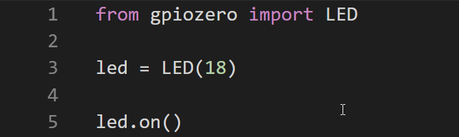
Images courtesy of MakeUseOf
This may not seem like a big deal, but if you plan on using a bunch of already pre-configured hardware modules that also have software modules developed, the GPIO Zero library will save you a lot of time.
Working with Python Libraries
First, you’ll need to have Python installed on your computer.
Next, it’s time to choose a library. As mentioned, I recommend the GPIO Zero and/or the RPi.GPIO libraries. If you’re 100% new to programming electronics (no Arduino or Python experience), then I recommend using the GPIO Zero library.
If you’re coming from the world of Arduino, then you may want to play around with both. The RPi.GPIO library is most similar to how you’d program I/O on Arduino.
Install the library according to its documentation. Then, swing back here for some example projects.
Useful Raspberry Pi GPIO Zero Examples
There are a TON of GPIO Zero example projects in the documentation. I highly recommend reading through each of them, and giving them a try. I know how overwhelming so many examples can be, so I wrote this section is to point you to a few really useful examples from that documentation.
LED with Variable Brightness: This example will show you not only how to control an LED, but also how to use PWM with the Raspberry Pi GPIO.
Measure Temperature with an ADC: Here’s how to get your Analog sensor working with an external ADC (MCP3008). The cool part about this example, is that the MCP3008 software module is written indifferent to the sensor that’s connected to it. This means you can use this setup for just about any analog sensor.
Keyboard Controlled Robot: I like this example because it shows you how to interface a motor controller (SN754410) with inputs from your keyboard. It’s a great project that highlights integration of many parts.
There are a bunch more examples that you can try, so be sure to check those out and leave a comment below with your favorite one!
Also, don’t forget to Follow & Tag me in your robotics projects on Instagram @learnrobotics.
Consider supporting the blog and the work I do by buying me a coffee.