

In this tutorial, I will share with you how to make a smart robotic arm. You can control this arm using a “Master” arm using potentiometers. The “Slave” arm is comprised of servos and will run off of the potentiometer readings. This will mimic manual movements. Along with this feature, the prototype is also smart because it can record positions and repeat them continuously.
This project is designed for people with experience using Arduino and electronics. Therefore, I wouldn’t recommend this project to absolute beginners. You need basic understanding of using Servos, potentiometers, and programming knowledge.
Things You Will Need
- Arduino UNO ( Arduino Nano or Arduino Mega ) x 1
- Micro Servos ( Standard Servos ) x 5
- 10k ohm Potentiometers x 5
- Breadboard Kit
Note: You can increase the number of joints to increase range of motion by increasing servos and potentiometers.
If you want to make your own arm you can use an Acrylic sheet or Popsicle sticks. As I have used. You can even 3D print a design or use a CNC machine. Another option is to buy a Robotic Arm Kit, which consists of everything needed for this project.
Making The Arms
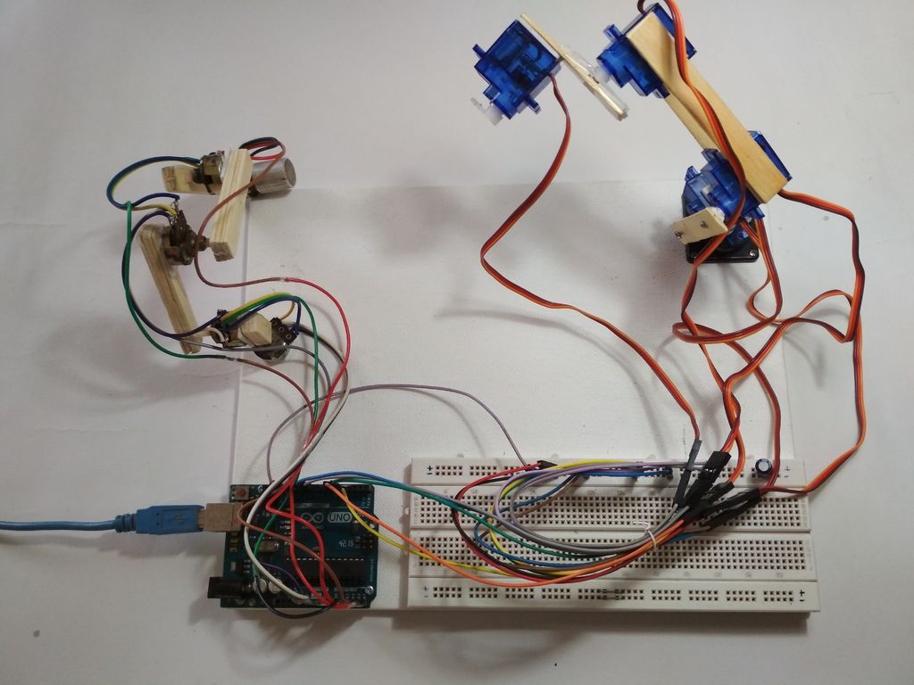
Here I have used Popsicle sticks to make the arm. You can use any materiel that is available to you. And you can try different mechanical designs to make even better arm. My design (shown above) is not very stable and does not have a gripper. I used double sided tape to stick the servos to the Popsicle stick and fasten them using screws. For the Master arm I glued the potentiometers to the popsicle sticks. Check out the picture to get a better idea of how this looks. Lastly, I mounted everything on a poster board, which was used as base. When you’re done building the prototype, then you can move onto wiring up the electronics.
Wire up the Servos
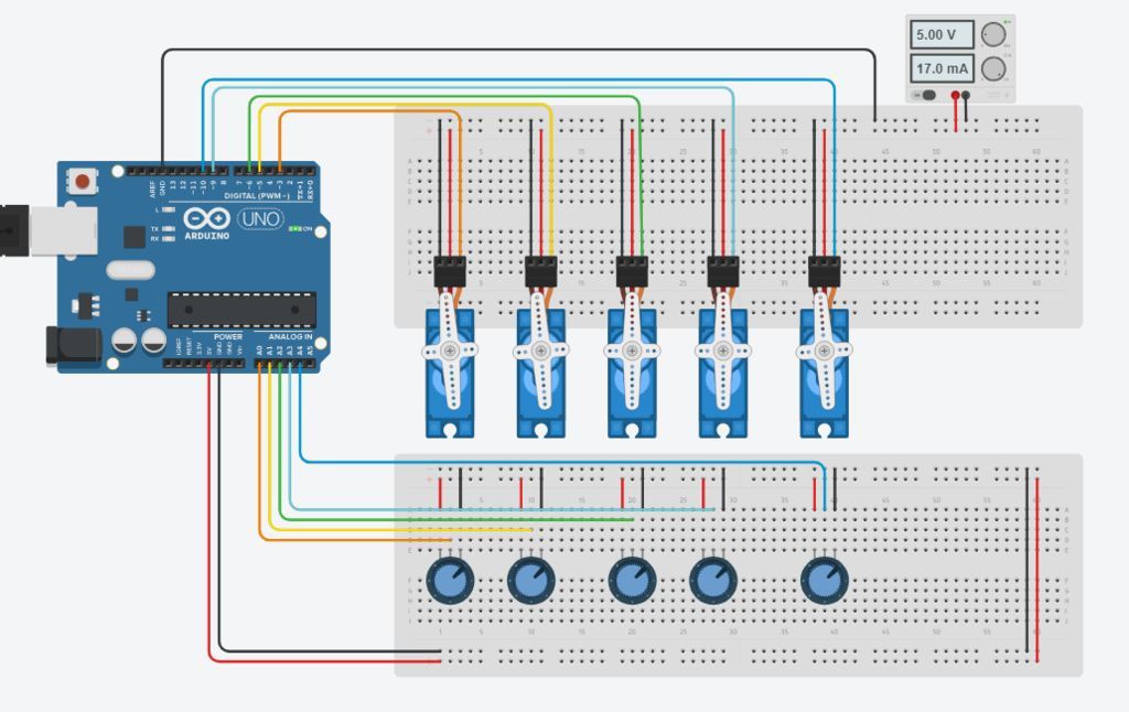
In this step we will make all the necessary connections. Use the picture above as a reference. If you’ve never used a breadboard before, we recommend checking out this article.
First connect all the servos in parallel to the power supply. (The Red wire to +5V and Black or Brown Wire to GND). Next, connect the signal wires i.e Yellow or Orange wire to the PWM pin of the Arduino. Now connect the potentiometers to +5v and GND of Arduino in parallel. Then, connect the middle terminal to Analog pin of the Arduino. We will use Digital Pins 3,5,6,9 & 10 to control the servos Analog Pins A0 to A4 are used for Input from Potentiometers. The servo connected to pin 3 will be controlled by the potentiometer connected to A0. Lastly, the servo connected to pin 5 will be controlled by the potentiometer on A1, and so on….
Note: The Servos are powered by a separate power supply (not the Arduino). Make sure to connect the GN of the servos to the Arduino or else the arm wont work. This system requires a shared ground between the controller and the power supply.
How to Code the Smart Robotic Arm
The logic of this code is fairly simple the values of potentiometers are stored in an array the records are then traversed using a for loop and the servos do the steps as per the values. You can download the sample code below.
[pretty-locker id=”339508″]Now let us understand the code step-by-step.
1. Declare Global Variables
First we will declare all the necessary variables globally so we can use them throughout the program. No special explanation is needed for this.
#include <Servo.h>

//Servo Objects
Servo Servo_0;
Servo Servo_1;
Servo Servo_2;
Servo Servo_3;
Servo Servo_4;

//Potentiometer Objects
int Pot_0;
int Pot_1;
int Pot_2;
int Pot_3;
int Pot_4;

//Variable to store Servo Position
int Servo_0_Pos;
int Servo_1_Pos;
int Servo_2_Pos;
int Servo_3_Pos;
int Servo_4_Pos;

//Variable to store Previous position values
int Prev_0_Pos;
int Prev_1_Pos;
int Prev_2_Pos;
int Prev_3_Pos;
int Prev_4_Pos;

//Variable to store Current position values
int Current_0_Pos;
int Current_1_Pos;
int Current_2_Pos;
int Current_3_Pos;
int Current_4_Pos;


int Servo_Position; //Stores the angle
int Servo_Number; //Stores no of servo

int Storage[600]; //Array to store data (Increasing array size will consume more memory)
int Index = 0; // Array index starts from 0th position
char data = 0; //variable to store data from serial input.
2. Write the Setup Method
Now we will write a setup function, where we set pins and their functions. This is the initialization function that executes once upon controller startup.
void setup()
{
  Serial.begin(9600); //For Serial communication between arduino and IDE.

  //Servo objects are attached to PWM pins.
  Servo_0.attach(3);
  Servo_1.attach(5);
  Servo_2.attach(6);
  Servo_3.attach(9);
  Servo_4.attach(10);

  //Servos are set to 100 position at initialization.
  Servo_0.write(100);
  Servo_1.write(100);
  Servo_2.write(100);
  Servo_3.write(100);
  Servo_4.write(100);

  Serial.println("Press 'R' to Record and 'P' to play");
}
3. Read & Map Potentiometer Values to the Servos
Now, we will read the values of potentiometers using Analog Input pins and map them to control servos. For this we will define a function and name it Map_Pot() you can name it anything you want it is a user defined function.
void Map_Pot()
{
 /* The servos rotate at 180 degrees
    but to using it to limits is not
    a good idea as it makes the servos buzz continuously
    which is annoying so we limit the servo to move
    between: 1-179 */

   Pot_0 = analogRead(A0);               // Read input from pot and store it in the Variable Pot_0.
   Servo_0_Pos = map(Pot_0, 0, 1023, 1, 179); //Map servos as per the value between 0 to 1023
   Servo_0.write(Servo_0_Pos);           //Move the servo to that position.

   Pot_1 = analogRead(A1);
   Servo_1_Pos = map(Pot_1, 0, 1023, 1, 179);
   Servo_1.write(Servo_1_Pos);

   Pot_2 = analogRead(A2);
   Servo_2_Pos = map(Pot_2, 0, 1023, 1, 179);
   Servo_2.write(Servo_2_Pos);

   Pot_3 = analogRead(A3);
   Servo_3_Pos = map(Pot_3, 0, 1023, 1, 179);
   Servo_3.write(Servo_3_Pos);

   Pot_4 = analogRead(A4);
   Servo_4_Pos  = map(Pot_4, 0, 1023 , 1, 179);
   Servo_4.write(Servo_4_Pos);
}
4. Call Functions within Loop
Next, we will write loop() function as :
void loop()
{
   Map_Pot();  //Function call to read pot values

   while (Serial.available() > 0)
   {
     data = Serial.read();
     if (data == 'R')
     Serial.println("Recording Moves...");
     if (data == 'P')
     Serial.println("Playing Recorded Moves...");
   }

  if (data == 'R') //If 'R' is entered, start recording.
  {

    //Store the values in a variable
    Prev_0_Pos = Servo_0_Pos;
    Prev_1_Pos = Servo_1_Pos;
    Prev_2_Pos = Servo_2_Pos;
    Prev_3_Pos = Servo_3_Pos;
    Prev_4_Pos = Servo_4_Pos;

    Map_Pot();  // Map  function recalled for comparison

    if (abs(Prev_0_Pos == Servo_0_Pos)) // absolute value is obtained by comparing
    {
      Servo_0.write(Servo_0_Pos); // If values match servo is repositioned
      if (Current_0_Pos != Servo_0_Pos)  // If values don't match
    {
        Storage[Index] = Servo_0_Pos + 0; // Value is added to array
        Index++;  // Index value incremented by 1
      }
      Current_0_Pos = Servo_0_Pos;
    }

    /* Similarly the value comparison is done for all the servos, +100 is added every for entry
       as a differential value. */

    if (abs(Prev_1_Pos == Servo_1_Pos))
    {
      Servo_1.write(Servo_1_Pos);
      if (Current_1_Pos != Servo_1_Pos)
      {
        Storage[Index] = Servo_1_Pos + 100;
        Index++;
    }
     Current_1_Pos = Servo_1_Pos;
   }


   if (abs(Prev_2_Pos == Servo_2_Pos))
   {
     Servo_2.write(Servo_2_Pos);
     if (Current_2_Pos != Servo_2_Pos)
     {
       Storage[Index] = Servo_2_Pos + 200;
       Index++;
     }
    Current_2_Pos = Servo_2_Pos;
   }


   if (abs(Prev_3_Pos == Servo_3_Pos))
   {
     Servo_3.write(Servo_3_Pos);
     if (Current_3_Pos != Servo_3_Pos)
     {
       Storage[Index] = Servo_3_Pos + 300;
       Index++;
     }
     Current_3_Pos = Servo_3_Pos;
   }
   if (abs(Prev_4_Pos == Servo_4_Pos))
   {
     Servo_4.write(Servo_4_Pos);
     if (Current_4_Pos != Servo_4_Pos)
     {
      Storage[Index] = Servo_4_Pos + 400;
      Index++;
     }
    Current_4_Pos = Servo_4_Pos;
  }

  /* Values are printed on serial monitor, '\t' is for displaying values in tabular format */
  Serial.print(Servo_0_Pos);
  Serial.print(" \t ");
  Serial.print(Servo_1_Pos);
  Serial.print(" \t ");
  Serial.print(Servo_2_Pos);
  Serial.print(" \t ");
  Serial.print(Servo_3_Pos);
  Serial.print(" \t ");
  Serial.println(Servo_4_Pos);
  Serial.print ("Index = ");
  Serial.println(Index);
  delay(50);
  }

  if (data == 'P') //IF 'P' is entered , Start playing recorded moves.
  {
    for (int i = 0; i < Index; i++) //Traverse the array using for loop
    {
      Servo_Number = Storage[i] / 100;  // Finds number of servo
      Servo_Position = Storage[i] % 100; // Finds position of servo

      switch(Servo_Number)
      {
        case 0:
             Servo_0.write(Servo_Position);
             break;

        case 1:
             Servo_1.write(Servo_Position);
             break;

        case 2:
             Servo_2.write(Servo_Position);
             break;

        case 3:
             Servo_3.write(Servo_Position);
             break;

        case 4:
             Servo_4.write(Servo_Position);
             break;
       }
     delay(50);
   }
 }
}
Once the code is ready, upload it to the Arduino board. With that finished, the Smart Arm is ready to test!
How to Test the Smart Robot Arm
After uploading the code to the board, open the ‘Serial Monitor’. (Click the magnifying glass in the top right corner, or go under Tools > Serial Monitor.) When the Serial Monitor starts, the Arduino will reset. Now you can control the robotic arm using the master arm.
Recording Positions with the Master Arm
Positions won’t be recorded until you initialize the recording command. To start recording, open the Serial Monitor, press the ‘R’ key, and hit Enter. Now you can perform the moves you wish to record. After the moves are done you can press the ‘P’ key to play the recorded moves. The servos will continue to perform the moves as long as the board is not reset.
I hope you enjoyed this tutorial, and you learned something new. Experiment with this project, improve the code, and share your results. I am happy to see what you make! As always comment below with any questions!


2 Responses
many big thanks, if i want to put the recorded movement of the slave in a repeat position, how do i modify the code?
Opeyemi, you’re welcome. I’m not sure I fully understand your question. If you’re looking to “replay” a previously recorded position, you could store the recorded position into a variable or array and call that position by assigning it to a keystroke.