

Are you looking to interface Raspberry Pi with a servo motor? Are you confused about how servo motors work?
Well, you’ve come to the right place! In this article, I will show you how to wire and program servo motors using Python and demystify the concept of the “duty cycle” to calculate the servo angle.
Ready to get started?
Servo Motor vs. DC Motor
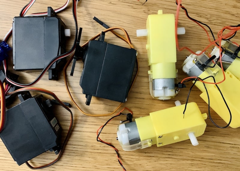
What is a servo motor? A servo motor is a type of DC motor that can rotate to a specified angle. A DC Motor is a type of motor that converts electrical energy into mechanical energy using a magnetic force. The difference between a servo motor vs. a DC motor is that you can control the angle of a servo motor whereas with a DC motor you can only control whether the motor is on or off.
If you want to control the speed, direction, and position of a DC motor, you’ll need to use a motor controller and an encoder, respectively. (I recommend the L298N.) The biggest advantage of servo motors is that you can precisely control the angle of the servo. Unlike DC motors, you won’t need any additional sensors to achieve degree-level precision and accuracy.
Another advantage of using servo motors is that you don’t need a motor controller. You can connect a servo motor directly to the pins on the majority of controllers (Raspberry Pi and Arduino) without using an intermediary chip. This makes wiring and configuration super easy.
Types of Servo Motors
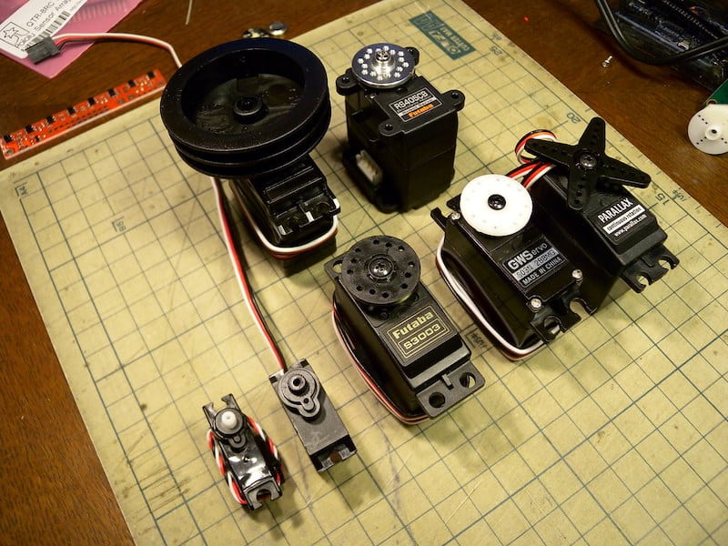
Most servo motors are not continuous. That means they cannot rotate a full 360 degrees. Most servo motors have a range of 0-180 degrees. Check the datasheet for your servo to determine its minimum and maximum positions. Three types of Servo motors that are popular are the 9g Servo Motor, the MG996R Servo Motor, and the Continuous Rotation Servo Motor.
9g Servo Motor
If you’re into robotics or hobby projects, the SG90 9g Servo motor (datasheet) is a popular choice. The SG90 is a small and lightweight servo motor with high output power. It can rotate 180 degrees (90 in either direction). Like traditional servo motors, this motor has three wires (ground, signal, and power).
[amazon box=”B07L2SF3R4,B07MFK266B,” template=”list”]MG996R Servo Motor
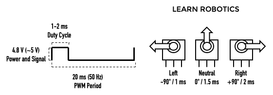
Another popular servo motor is the MG996R high-torque digital servo. It can rotate 120 degrees (60 in either direction). Both the SG90 and the MG996R have a similar Duty Cycle and PWM period. I’ve included the PWM diagram and angular rotation charts, below.
You can control the servo by providing a duty cycle (%) or converting the duty cycle to an angle measurement (in degrees). Click here to view the calculations.
Continuous Rotation Servo
A continuous rotation servo (like the FT90R servo) rotates 360 degrees. This is a great option if you want to build a mobile robot without using a motor controller or if you need high precision over 360 degrees of rotation. One thing to note is that as with most hobby servos, stalling or back-driving servos can damage it.
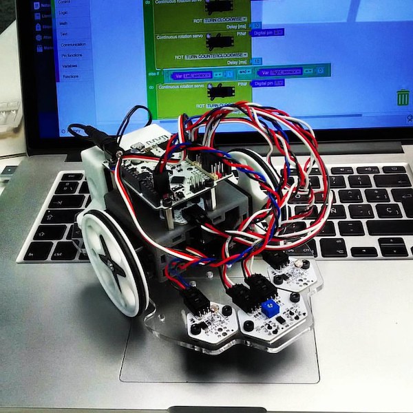
Servo Motor Control using PWM with Raspberry Pi
Servos are controlled using a Pulse-Width Modulation (PWM) signal from the Raspberry Pi. PWM is a type of digital signal that allows us to control devices in an analog fashion. PWM varies the amount of time a signal is HIGH or LOW.
As a result, we get a variable signal that can be used to control the angle of a Servo motor. In this section, you’ll learn how to calculate the duty cycle for your servo motor using the datasheet. We’ll use the popular SG90 9g servo as an example; however, this methodology can be used for the majority of off-the-shelf servo motors.
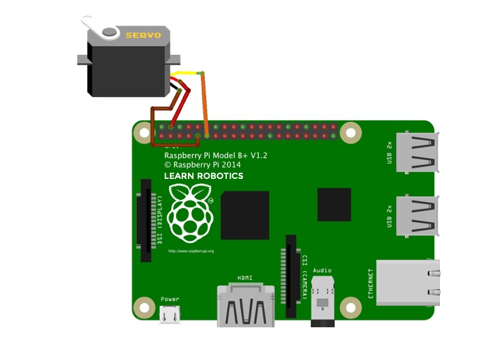
[amazon box=”B07V5JTMV9,B079FRHBTR” template=”list”]Step 1. Connect the Servo Motor to the Raspberry Pi using the Wiring Diagram
Here’s a Servo Motor Wiring Diagram for Arduino. All you need is a Raspberry Pi, 3 jumper wires, and a Servo Motor. You can also purchase a kit that has all of these components. Servo motors have three wires (ground, signal, and power). First, attach the ground wire to GND on the Raspberry Pi. Next, connect the signal wire to a GPIO pin on the Raspberry Pi. Finally, attach the power pin to 5V on the Raspberry Pi.
Once you have the servo motor wired to the Raspberry Pi, it’s time to run some tests to verify servo positions.
Step 2. Verify servo motor positions using the Raspberry Pi Example Code
First, grab a copy of the servo’s datasheet. Then, look for the PWM diagram. You want to find the duty cycle range and/or the “neutral” position pulse duration.
Once you have those, I recommend creating a three-position chart for left, neutral (center), and right. Annotate your diagram with the angle (degrees) and Duty Cycle (ms) for each of the three positions. See the chart below.
Next, convert the duty cycle times to percentages by dividing the position’s duty cycle by the total PWM Period (20 ms). For example, the left position has a duty cycle = 1 ms. Therefore, 1/20 x 100% = 5%. I’ve included this handy chart for your reference.
| Left | Neutral | Right | |
|---|---|---|---|
| Angle (deg) | -90 | 0 | +90 |
| Duty Cycle (ms) | 1 ms | 1.5 ms | 2 ms |
| Duty Cycle (%) | 5% | 7.5% | 10% |
Now that you have the duty cycle percentages for the three positions, it’s time to verify that these percentages accurately represent each of these positions. We’ll do this by using the RPi.GPIO library and writing Python code on the Raspberry Pi.
First, import the RPi.GPIO library and the sleep function.
import RPi.GPIO as GPIO
from time import sleep
Then, setup the GPIO mode as BOARD so that you can reference the PINs and not the BCM pins. (Feel free to use the BCM pins. If you come from the Arduino world, the Board pins will make more sense.)
GPIO.setmode(GPIO.BOARD)
GPIO.setup(11, GPIO.OUT)
I connected the servo motor to pin 11 (BCM GPIO17) on the Raspberry Pi.
Next, create a variable for the servo. I called mine “PWM.” Then, send a 50 Hz PWM signal on that GPIO pin using the GPIO.PWM() function. Start the signal at 0.
pwm=GPIO.PWM(11, 50)
pwm.start(0)
We’re almost ready to run our tests. Use the ChangeDutyCycle() function to write duty cycle percentages to the servo motor. Use the three duty cycle percentages calculated at the beginning of this step. You can reference the table above for the SG90 9g servo motor. (Left -90 deg is 5%, Neutral is 7.5%, and Right +90 deg is 10%.) Give the servo 1 second to reach its position.
pwm.ChangeDutyCycle(5) # left -90 deg position
sleep(1)
pwm.ChangeDutyCycle(7.5) # neutral position
sleep(1)
pwm.ChangeDutyCycle(10) # right +90 deg position
sleep(1)
Lastly, clean up the code by stopping the PWM signal and running the cleanup function on the GPIO pins.
pwm.stop()
GPIO.cleanup()
Save your program and then run it on the Pi. Verify the positions are correct. If they aren’t, make adjustments to the duty cycle percentages. When I ran this test, I had a range of 2% to 12%, not 5% to 10%. You can also use this method to calibrate the duty cycle range for other servo motors.
Save time and download the test code for free, below!
Here’s your download!
Servo Test Example Code (.py)
Step 3. Calculate “duty cycle to degrees” formula for the Servo Motor
The servo motor easily accepts a duty cycle percentage in the Raspberry Pi Python code. Rather than going through the process of manually calculating a percentage for the angle we want to reach, let’s create a formula to convert the duty cycle percentage to angle measurement in degrees.
Angles are a lot easier for humans to define, plus, we can utilize our Python code to run all the calculations for us.
To do this, we’ll create two ratios of known values based on a linear relationship between the Duty Cycle % and Desired Angle. Thanks to Marcelo Rovai for sharing this methodology!
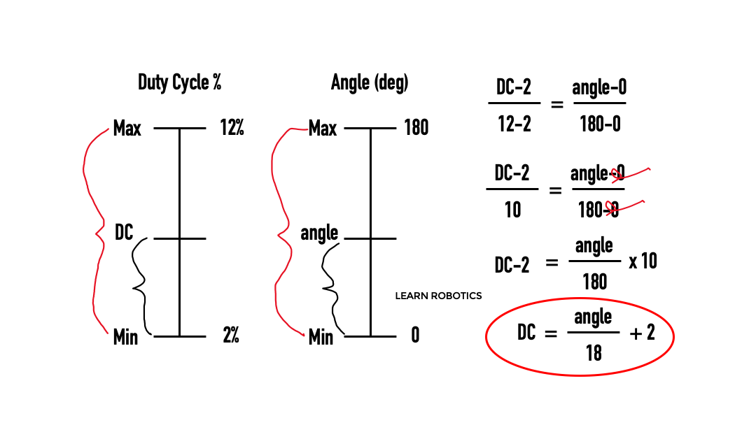
Now, you can create a Python function based on this formula to calculate the duty cycle percentage based on a given angle.
def setAngle(angle):
    duty = angle / 18 + 3
    GPIO.output(11, True)
    pwm.ChangeDutyCycle(duty)
    sleep(1)
    GPIO.output(11, False)
    pwm.ChangeDutyCycle(duty)
To set the servo to 35 degrees, you can use the command, setAngle(35) in your program. Pretty easy, right?!
Save time and download the Python Servo code for Raspberry Pi.
Here’s your download!
Servo Example Code for Raspberry Pi (.py)
Servo Motors are Easy to Control
You can think of the duty cycle as a percentage of time that the servo is receiving a high signal from the Raspberry Pi. The longer the duty cycle, the farther right the servo will rotate. From this example, we used the datasheet to determine three positions of the servo horn.
Then, we verified these positions using Python. Lastly, we created a formula to convert an angle to a percentage duty cycle. As a result, we can control the servo with degree-level accuracy.
While this concept might be confusing or convoluted at first, you can use a linear relationship and a set of equivalent ratios to determine the duty cycle formula for your servo motors. All you need is to capture those three positions and substitute the values into the formula in Step 3, above.
Servos are heavily application-based, so depending on how you mount the servo and what you’re trying to move, you’ll have to run some additional tests. I’ve included some example servo projects that you can try with both Raspberry Pi and Arduino.
Servo Motor Applications
Now that you know the basics of servo motor control, here are some servo motor applications that you can try!
- Pan-Tilt Servo Assembly Guide
- Pan-Tile Servo Programming Guide
- Face Tracking Camera with Servos and OpenCV
- Servo with HC-SR04 Ultrasonic Sensor
Regardless of what you make with your servo motors, you should have a pretty solid foundation in how servos work and how to use them in your next robotics or electronics application.
If you have any questions feel free to leave a comment below. Try one of these projects? Be sure to tag us on Instagram @learnrobotics.


14 Responses
The explanations were very detailed, thank you
Thank you!
I’m here, thank you for your article, it’s great, but do I have to use a rotating servo motor? If it is other, will there be any changes? okmarts mall
Depends on what you’re trying to build. If you’re not rotating, then why do you need a motor? ~Liz from Learn Robotics