

In this tutorial, I’m going to show you how to take a potentiometer reading and map it to a micro servo position. This is useful if you have a project where you want to convert readings from a sensor across one range, into readings that can be used to set a position in another range. More specifically, in this project, we’ll look at how to convert a 10-bit analog signal (0-1023) into an angular measurement from 0-180 degrees. If you’re looking for a way to implement manual servo control, want to fine-tune servo position, or you want to be able to take readings and convert them from one set of values to another set of values, then you’ll want to stay tuned for this tutorial.
Word to the wise: this is an intermediate project. We won’t cover the basics of circuits and electronic programming; however, these are concepts I cover in-depth in my Arduino for Beginners course. I highly recommend starting in Arduino for Beginners if you’re new to circuits and coding and want to gain familiarity with writing and creating electronics projects like this one. Sign up and gain immediate access to lessons and projects, today!
Step 1. Wire the Servo and Potentiometer Circuit to Arduino
First, connect the potentiometer to the analog input pin, A4, on the Arduino. Then attach the servo motor to digital output ~3. Here’s a wiring diagram that you can use as a reference. 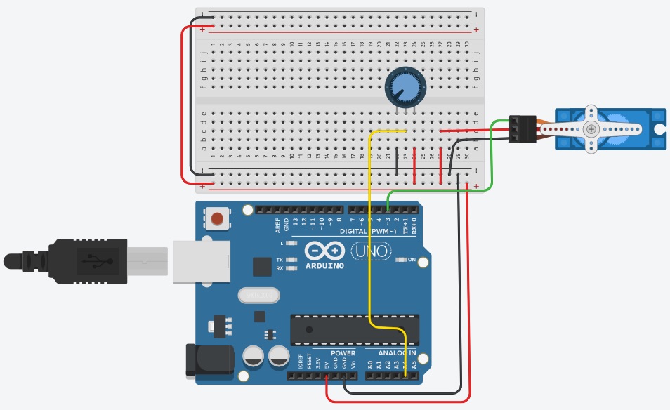 You can connect the servo motor to any of the PWM-enabled pins (marked ~) on the Arduino. After you have your circuit wired, move to Step 2 to start writing the code.
Step 2. Set up the Software-Hardware Interface
Next, let’s set up the code to interface this hardware with our Arduino program. Open up the Arduino IDE, and create a new sketch. Import the Servo library and create a servo object. Then, create a global variable for the potentiometer and set it equal to A4.
#include
Servo myServo;
int POT = A4;
int reading, newPos, currMap, num; //globals added in later steps
Then, write the setup() method to set the potentiometer as an INPUT. Attach the servo motor to pin 3. Now’s a good time to initialize the Serial Monitor to 9600 baud. That way we can use it to print out readings for our potentiometer and servo angle measurements.
void setup()
{
  myServo.attach(3);
  pinMode(POT, INPUT);
  Serial.begin(9600);
}
Once your program is set up, it’s time to create the two important methods for this project. The first method will get the current position of the potentiometer. The second method will convert the potentiometer reading into an angular measurement and set the servo motor. Let’s walk through these methods in the next two steps.
Step 3. Create a Method to Collect Potentiometer Positions
The purpose of this method is to read the current position of the potentiometer and then return the value. We’ll use this reading in Step 4 to convert it to an angle measurement for the servo motor.
int readPot(){
  int curr;
  if(curr != reading){
    reading = analogRead(POT);
    curr = reading;
  }
  return curr;
}
First, create a local variable, curr, to store the current reading. Then check to see if we’ve received a new reading from the potentiometer. If so, we’ll update the current reading and return it. If not, keep the current reading. That way we’re not collecting and setting the same reading repetitively. Now that we have our reading from the potentiometer, it’s time to use it to set the servo angle position. [amazon box=”B07C3XHVXV,B07MLR1498,B01DGD2GAO” template=”list”]
Step 4. Use Potentiometer Positions to Map to Servo Positions
Since analog sensors are a 10-bit signal, we’ll receive a reading in the range of 0-1023. If we use this raw value with our servo, only the values 0-180 will set a position, which is only utilizing 17.5% of the range on our potentiometer. As a result, our system wouldn’t represent the full input range as the output on our servo. You can play around with the mapping idea and see how it works if you don’t convert the input readings to a range of 0-180. You’ll probably notice how “easy” it is to move the servo from 0-180 without utilizing the full sweep of the potentiometer. That’s why we want to “map” the servo readings into a corresponding angle position. This process “shrinks” the 0-1023 range into a 0-180 degree range by creating a map. To get the output angle, we have to multiply the input reading by 0.1759. (The maximum of the input divided by the maximum of the output = 1023/180 = 0.1759.) Fortunately, the Arduino library has a built-in method called map(), which does this conversion calculation for us. Here’s what the code looks like:
void mapServo(int pos){
  int curr;
  num = map(pos, 0, 1023, 0, 180);
  myServo.write(num);
  delay(50);
}
After we convert the input position to an angle, we can use the servo write() method to control the servo.
Step 5. Print Out Readings to the Serial Monitor
Once you’ve got these methods written, it’s time to call them in loop(). Remember, the loop() method contains all of the code that runs on the Arduino. If you forget to call auxiliary methods in loop(), then it won’t run on the board. You can stop here and the project will work as expected. However, if you want to see the potentiometer input values and the servo output angles, you can write these values to the Serial Monitor for testing.
void loop()
{
  newPos = readPot();
  mapServo(newPos);

  if(currMap != newPos){
    Serial.print("Pot Position = ");
    Serial.print(newPos);
    Serial.print(" Servo Angle = ");
    Serial.println(num);
    currMap = newPos;
  }
}
Similarly to collecting potentiometer readings, you can check to see if the value has changed and then print out the values for the potentiometer and the servo angle to the Serial monitor. This is to prevent the Serial Monitor from constantly printing out the same readings continuously, which makes it very difficult to read the values. Then, when you run your tests, you’ll be able to see the exact numbers and use them to hardcode values into projects or fine-tune measurements. And that’s it!
How you can use this project
This project is helpful if you’re trying to tune servos or if you want to figure out what positions are great for your application. You can use this project to easily figure out how the input positions from a sensor map to the output or desired position on your servo motor. Plus, it’s an easy way to get user input and dynamically change the servo write value without having to hard-code anything. Mapping a potentiometer to a servo motor makes it super easy to print out values on both sides (inputs and outputs) and see how they’re mapping in a range while testing on the fly.
How are you planning on using this project? Be sure to leave a comment below! And, if you enjoyed this type of content be sure to share it on your favorite Social Media platform.
Interested in Gaining Skills through Tech Projects?
Go from zero circuit and coding skills to prototyping! If you have an interest in electronics and want to build the skills needed to design your own devices, then you’ll want to check out our Level 1 online course. Students of all ages (and adults) have had success in our self-paced program.
You can now learn how to build circuits, create IoT Smart Homes, and robotics projects from Start to Finish. Now’s the best time to start building projects from home and boost your tech, coding, and robotics skills! Click here to learn more.


2 Responses
Hey Liz. There is confusion about the analog input. At start A2 is mentioned as where to connect pot, but in code A4 is used.
Hey Terry! Good catch. We’ve updated the article to show the POT on A4. For reference, it doesn’t matter which analog pin you use, as long as both the hardware connection and the software mapping match. Hope this helps! ~Liz from Learn Robotics