Welcome back to Beginner Bots Tutorial #2. This week, we are focusing on assembly, wiring, and learning about sensors. If you haven’t read Part 1 of How to Build a Mobile Robot using Arduino, I recommend checking that lesson out before starting this one!
Completely new to the world of robotics? Then, you’ll want to check out our Robotics eCourse. We expand upon these tutorials to give you a comprehensive introduction to robotics engineering. You’ll gain access to additional Mobile Robot projects, quizzes, and a Course Certificate. It’s a great way to highlight your experience on a College Application or Resume! Click here to Enroll.
Build a Mobile Robot Lesson #2 – Objectives & Materials
Each week I will provide you with the objectives (goals of the lesson) and any materials you will need to complete the project.
I absolutely LOVE seeing what you guys are working on, so please don’t forget to tag me (@learnrobotics) on Instagram and Facebook with any progress you’ve made!
Part 2 – Goals & Objectives
- Assemble the robot chassis
- Complete the robot wiring
- Learn about Analog & Digital sensors
- Understand Inputs & Outputs
- Create a simple program for Arduino
- Time Duration: Approximately 2 hours (Assembly could take longer depending on your experience.)
Part 2 – Materials for this Lesson
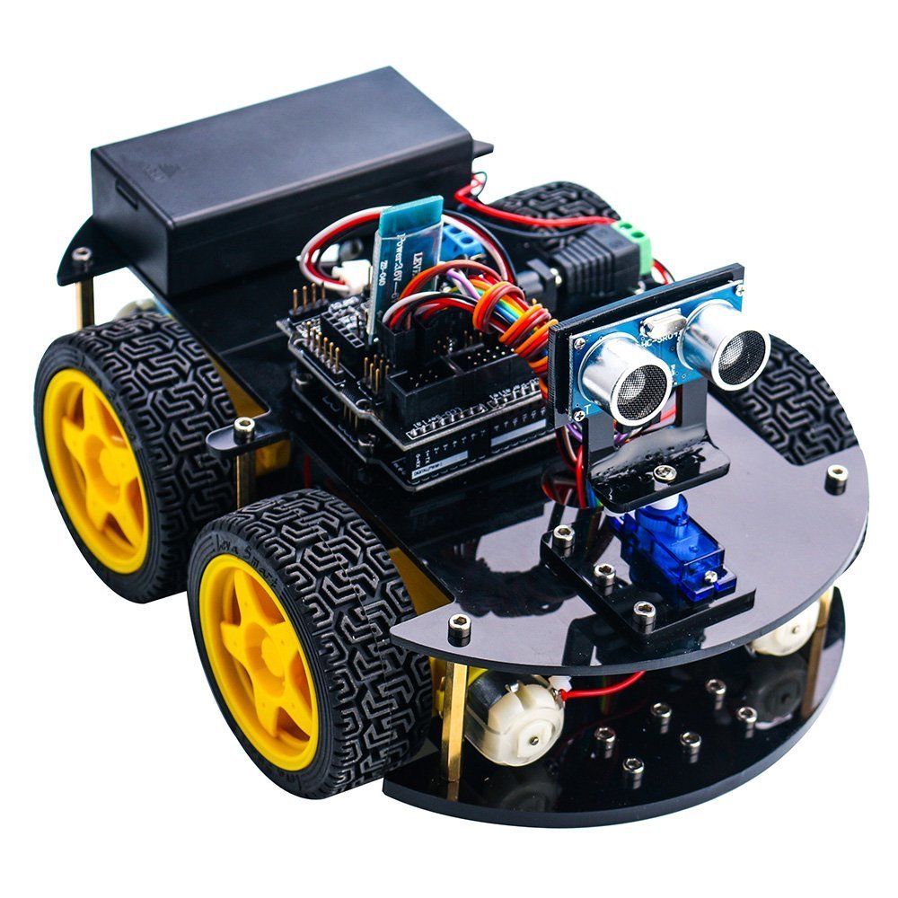
This tutorial series is based on the Elegoo Arduino Smart Robot Car kit. You can purchase the kit on Amazon for about $70. I recommend this kit because it provides a lot of value for the money and the components can be utilized in a number of robotic projects.
While you can follow along without purchasing the kit, it’s always more beneficial to be hands-on with a robot and try out the lessons for yourself. With that said, if you’re on a tight budget, I listed out the full components in Part 1 of this tutorial series.
Additional Materials
- Included in Elegoo Robot Kit:
- L298N
- Arduino Uno
- Arduino Uno Sensor Shield V5
Other Materials:
- Multimeter
- Multitool (I use a Leatherman Wingman)
- Wire Cutters/Strippers
- Household Tool Set
- Screwdriver Set
- Drill (Faster to construct everything)
- Computer with at least 1 USB port (any OS is fine)
It’s time to Assemble our Robot!
Build Your Robot!
This week’s focus is on robot construction.The video below shows how to assemble the Elegoo Arduino Smart Robot Car V3. Grab your tools, your robot kit, and let’s get started.
Note: If you have an earlier version of the Elegoo Smart Robot Car, then you will need to wire up the electronics a little differently. We will review the wiring in a later part of this tutorial, so don’t worry about that while you’re assembling the robot’s frame!
Download the build instructions, below! You can also enroll in the Full Robotics eCourse to gain access to step-by-step drawings, activities, quizzes, projects, and a Course Certificate. Click here to Learn More.
[pretty-locker id=”339508″]Click to Access the Build Instructions
I’ve summed up these instructions into four steps:
Step 1 – Connect the motors and wheels to the chassis.
Step 2 – Attach motor controller, Arduino Uno/Sensor Shield to the chassis
Step 3 – Assemble battery pack to Chassis
Step 4 – Continue on with the lesson, below (One Minute Lesson Analog vs. Digital)
One Minute Lesson: ANALOG vs. DIGITAL sensors
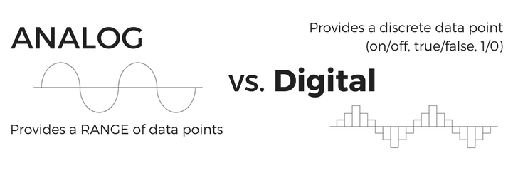
First, we will talk about sensors. There are 2 classifications of sensors we will be focusing on:
1. ANALOG: An analog sensor provides data within a range or span of numbers.
Some examples: light sensor, temperature sensor
2. DIGITAL: A digital sensor provides data that is either True or False, 1 or 0, off or on.
Some examples: push button, two-position switch
This is a very important concept, so I’ve included some additional resources below. The main reason why this is so important is because the Arduino has pins that are either Analog pins or Digital pins.
Therefore, if you plug an Analog sensor into a Digital pin, you may not receive the desired output for your robot.
Additional Resources
One Minute Lesson: INPUT vs. OUTPUT Electronics
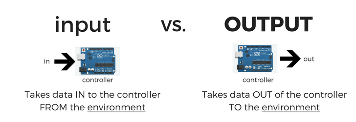
In addition to being Analog or Digital, sensors can be either INPUTS or OUTPUTS.
An input sensor brings data IN from the environment to the controller for processing. This is known as READING data. A common example is an Ultrasonic Sensor.
A output sensor produces data from the controller OUT to the environment. This is known as WRITING data. A common example is an LED (light emitting diode).
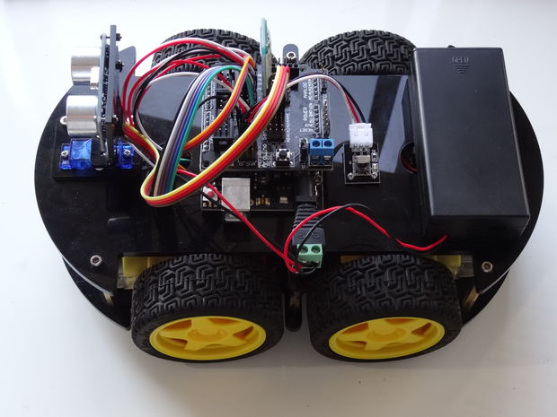
Wire it Up!
Now, we’ll connect motors and sensors to the Arduino Microcontroller & Motor controller.
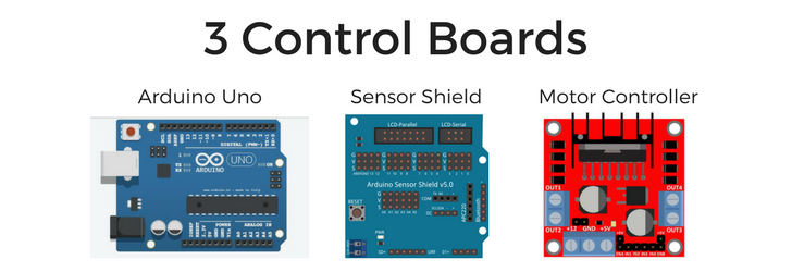
There are 3 key boards on our robot:
- Microcontroller (Arduino Uno R3): This is the board you program. Connect it via USB and you can access its pins to read & write data.
- Sensor Shield: This board connects over the top of the Arduino and provides additional sensor ports to support extra sensors.
- Motor Controller (L298N): This is the board that you will connect your motors to. You will then connect the motor controller to the Arduino for control.
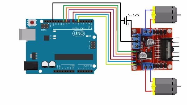
Wire up the Arduino Sensor Shield and Motor Controller using the picture above for reference.
Note: Your wire colors DO NOT need to match the wire colors in the diagram!
If you have the Elegoo Smart Robot Car V3, then you’ll want to connect the wires based on the provided connectors. It should look very similar to the diagram above, but rather than using individual wires, you will use the provided cables to connect each component.
Write some code!
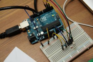
We’re going to create a simple sketch to blink an LED on the Arduino.
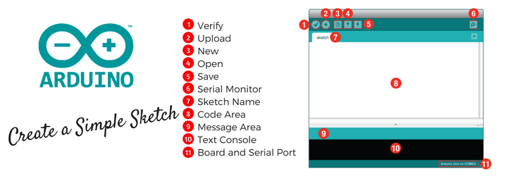
Next, create your first Arduino “Sketch” Arduino programs are called Sketches. Then, configure the sketch to turn the built-in LED on pin 13 on and off. This is a very common activity used to 1) verify the board is working and 2) understand how to write a simple program for Arduino.
- Connect the Arduino to your computer via the USB cord.
- Open Arduino IDE (local software or online compiler)
- File > New
- Copy and paste the following code into your sketch
/* Blink
* Written by Liz Miller from Learn Robotics
* Beginner Robot Course | www.learnrobotics.org
*/
//global variables- defined here
int ledPin=13; //built-in LED is on pin 13
//setup- required method for compiling
void setup(){
    pinMode(ledPin, OUTPUT); //LEDs are outputs
}
//loop- required method for compiling. runs forever.
void loop(){
    digitalWrite(ledPin, HIGH); //turn the led ON
    delay(5000); //delay 1000ms or 1sec
    digitalWrite(ledPin, LOW); //turn the led OFF
    delay(5000); //delay 1000ms or 1sec
}
- Save your program (File > Save)
- Configure your board (Click here for additional information on Arduino).
- Compile & Download
- You should see the LED blinking on pin 13 of the Arduino Uno!
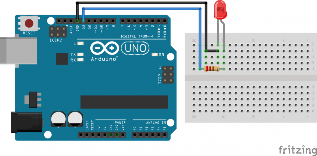
BONUS: If you have an LED and a 220ohm resistor, feel free to wire it up! Here’s a diagram for reference! The ledPin=13 in this example. The flat side of the LED is the NEGATIVE side.
In the next lesson we will talk about methods, variables, and writing code for the robot motors. We did a lot for this lesson, but if you’re ready for more, head on over to Part 3, and let’s get this robot moving!
If you liked this article, you’ll LOVE our eCourse!
Join our Robotics eCourse and go beyond these tutorials with interactive lessons, discussions, projects, and a course certificate! Click here to enroll.