

Cool Arduino Projects is a new tutorial series we’ve started on the Learn Robotics blog. The goal is to show you how to create application-based projects using Arduino. If you’re a teacher looking for a STEM project, you can use the full lesson plans in your class.
The Application: Ties to Math & Comp Sci
For today’s lesson, we’re going to create an Arduino dice. We’ll focus on wiring up LED’s and a push button as well as simple logic to “roll the dice.” In the next part of the lesson, we’ll connect an LCD and display information to our user. This project ties in nicely with topics in computer science, math/probability, and game design. Let’s get started!
Create a Prototype Arduino Dice
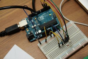
First, we’ll wire up the prototype circuit. You’ll need a breadboard, six LED’s, six 220Ω resistors, an assortment of jumper wires, an Arduino Uno, a push button, one 10KΩ resistor, and a USB printer cable. I recommend this Arduino kit because it includes a lot of components for the price.
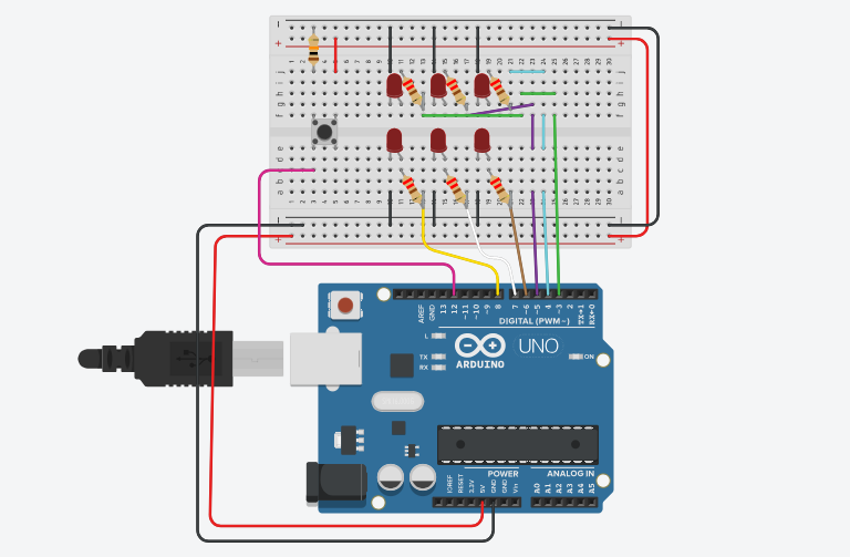
Here’s the wiring diagram for the circuit:
You can also use the simulated model on Tinkercad. This is a great way for each student to complete the lesson without the need for 1:1 kits.
Connect the LED’s
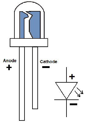 To start off, connect the LED’s to the breadboard. Remember that LED’s are polarized, so be sure to plug the positive (curved) side into a resistor and the negative (flat) side into ground. Each LED will be connected to a digital pin on the Arduino. In the wiring diagram, we’ve used digital pins 3-8 for LED’s.
Wire up the Push Button
Next, connect the button to the breadboard. One leg is connected to the 10KΩ resistor and to ground. Another leg will be connected to 5V, and a third leg will be connected to digital pin 12 on the Arduino.
Power the Circuit
Finally, assemble the power rails. Connect both power rails of the breadboard to each other. Then run jumper wires from 5V on the Arduino to the red power rail and GND on the Arduino to the black power rail. We’ll power the circuit using the USB printer cable and a USB port on our computer. Verify that the components are correctly wired before moving to the next step.
Program the Arduino for the Simulated Dice
Now, we’ve reached the fun part! Let’s program the Arduino to simulate a dice roll. You’ll need to have a copy of the Arduino IDE downloaded on your computer.
If you’re teaching this lesson as part of a class, students can create a “flowchart” or sequence of events outlining their code.
The Setup() method
The setup() method runs once on start-up. Define all the LED pins as OUTPUTS inside this method. Then initialize the Serial Monitor using the command Serial.begin(9600);
Your code should look something like this:
int button = 12;
//led's are on pins 3-8

void setup()
{
    pinMode(3, OUTPUT);
    pinMode(4, OUTPUT);
    pinMode(5, OUTPUT);
    pinMode(6, OUTPUT);
    pinMode(7, OUTPUT);
    pinMode(8, OUTPUT);
    pinMode(button, INPUT);

    Serial.begin (9600);
    Serial.println("Welcome to Arduino Dice");
    Serial.println("Press the button to roll a number");
}
You’ll notice I’ve included a couple of print statements to show the user we’ve initialized the dice. This can be accessed in the Serial Monitor of the Arduino IDE.
Code to “roll a dice”
To simulate a dice roll, we’ll use the built-in Arduino method, random().
First, we’ll create our random number, then we’ll use that number to illuminate the correct pattern of LED’s. Here’s an example of the code you can use.
[pretty-locker id=”339508″] int seed;
void displayNum(){
seed = random(1,6);
Serial.print(" You rolled a ");
Serial.println(seed);
//clear the previous display - shut off all LED's
for(int i =3; i<9; i++){
digitalWrite(i, LOW);
}
if(seed ==1){
digitalWrite(5, HIGH);
}
if(seed ==2){
digitalWrite(5, HIGH);
digitalWrite(7, HIGH);
}
if(seed ==3){
digitalWrite(4, HIGH);
digitalWrite(7, HIGH);
digitalWrite(3, HIGH);
}
if(seed ==4){
digitalWrite(3, HIGH);
digitalWrite(4, HIGH);
digitalWrite(6, HIGH);
digitalWrite(8, HIGH);
}
if(seed ==5){
digitalWrite(3, HIGH);
digitalWrite(4, HIGH);
digitalWrite(5, HIGH);
digitalWrite(6, HIGH);
digitalWrite(7, HIGH);
}
//all LED's on
if(seed ==6){
for(int i = 3; i < 9; i++){
digitalWrite(i, HIGH);
}
}
}
Next, we’ll call the displayNum() method in loop(). For now, we’ll run this method every 5 seconds (5000 milliseconds). Then, we’ll trigger the dice roll using a button. Verify that this works before moving to the next step.
https://www.instagram.com/p/BnRZ_DVgjJT/?taken-by=learnrobotics
Trigger Dice Roll with a Button
Congrats on making it this far! Now, let’s get the simulated dice to roll on a button press. In other words, when a user presses the button, the displayNum() method is triggered.
We’ll use a concept called “debouncing.” Push buttons often generate open/close states in a short amount of time. This is because of mechanical and wiring limitations. Therefore, in software we can account for this by checking twice in a short period. The code will ensure that the push button is definitely pressed.

Let’s modify the demo debouncing code to trigger the displayNum() method. I’ve created another method called rollDice() to store this code. Here’s what it looks like:
//additional global variables
int buttonState;
int lastButtonState = LOW;
unsigned long lastDebounceTime = 0;
unsigned long debounceDelay = 50;

void rollDice(){
  int reading = digitalRead(button);
  if (reading != lastButtonState) {
    lastDebounceTime = millis();
  }

  if ((millis() - lastDebounceTime) > debounceDelay) {
    if (reading != buttonState) {
      buttonState = reading;

      if (buttonState == HIGH) {
        displayNum();
        delay(1000);
      }
    }
  }
  lastButtonState = reading;
}
When you’re done, test it out by calling rollDice() in loop().
Further Learning
And that’s a wrap! I hope you enjoyed creating this Cool Arduino project! In the next lesson, we’ll add an LCD to display user information and probability calculations. If you enjoyed this project, be sure to leave a comment below.
You can also support Learn Robotics by downloading the full lesson plans including full code download, worksheets, PowerPoint slides, and rubrics here.


2 Responses
You should come up with an LCD version to play it at a board game. I personally will be working on this. but as a beginner I may not. Wish me Luck!!!!
Simon, yes that’s a good idea. Here’s an LCD tutorial that’ll help you get set up. The wiring is to a sensor shield, but you can go directly to the pins on your Arduino. The software configuration should be the same. Print the “random” code to the LCD instead of triggering LEDs. Good luck!